Problem
SAE Aero Design scores payload, so every choice in a competition aircraft wing is a trade against take-off weight, structural margin, manufacturability, and the competition rules. You cannot decide these one at a time. On the UTAT SAE Aero team I led wing aerodynamics and helped build a simple MDO loop for the aircraft so that aero, structures, and constraints could move together.
Approach
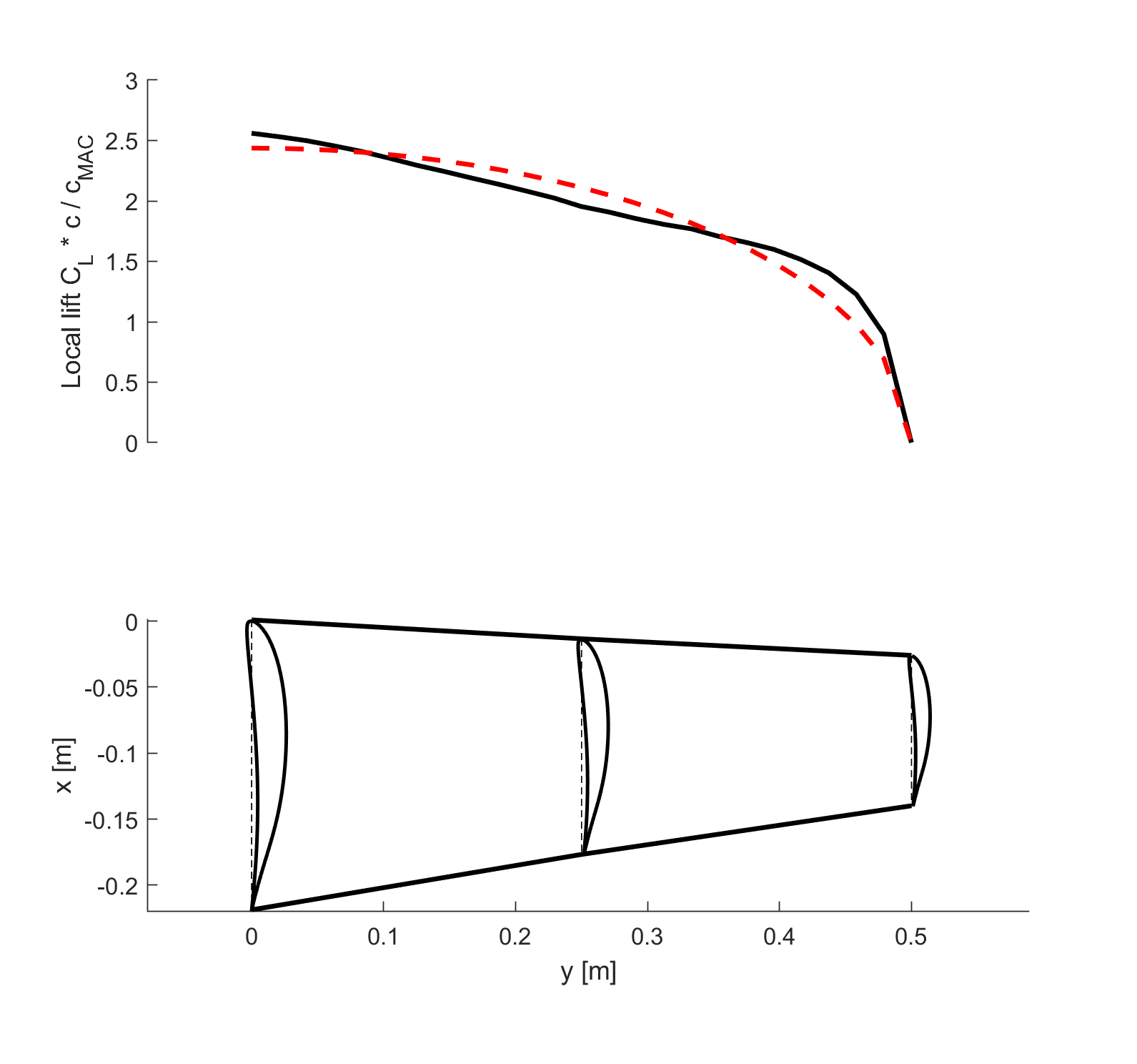
The loop coupled nonlinear lifting-line theory for spanwise loading with beam-bending spar sizing, wrapped in a small MATLAB optimiser around planform geometry and competition constraints. XFoil and XFLR5 supplied airfoil-level performance checks. The goal was MTOW and payload maximisation subject to stall, manoeuvrability, and structural limits, with results legible enough to be challenged by other leads.
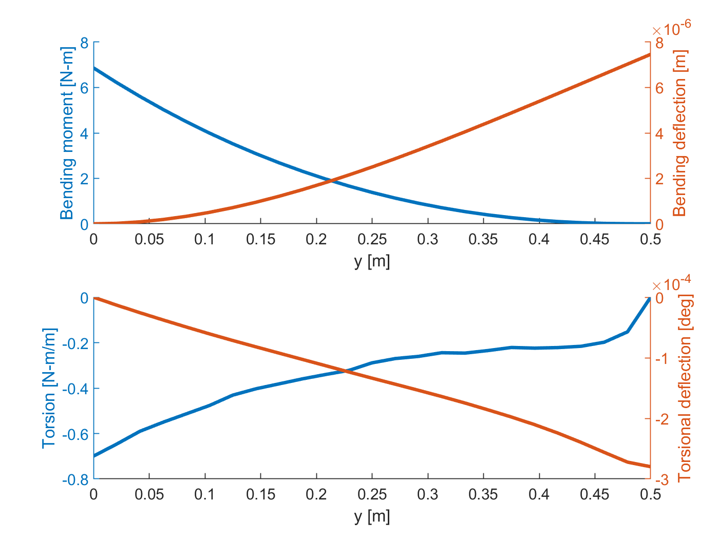
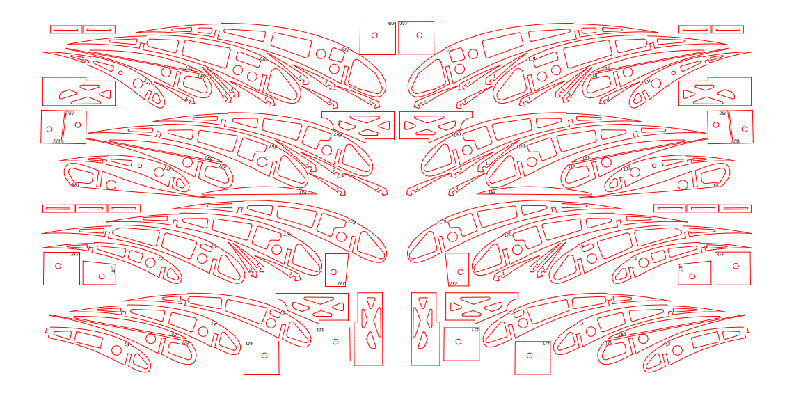
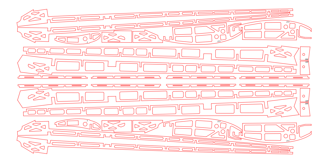
From-equations-to-hardware was the whole point. Lift distribution changes mean spar deflection changes; airfoil choice changes mean a different trailing-edge thickness in balsa and ply; aspect-ratio sweeps have to stop where manufacturability stops. The MDO loop was a way to make those couplings visible rather than implicit.
Result
A final planform — span, taper, aspect ratio — that met competition constraints with deliberate structural margin, paired with an airfoil chosen for high lift with a forgiving stall and a trailing edge that could actually be built. The MDO loop made the aero–structural trade visible: changes in aspect ratio and chord distribution came with explicit numbers for payload potential and spar demand, and every major choice was handed off to structures and manufacturing with a rationale attached.
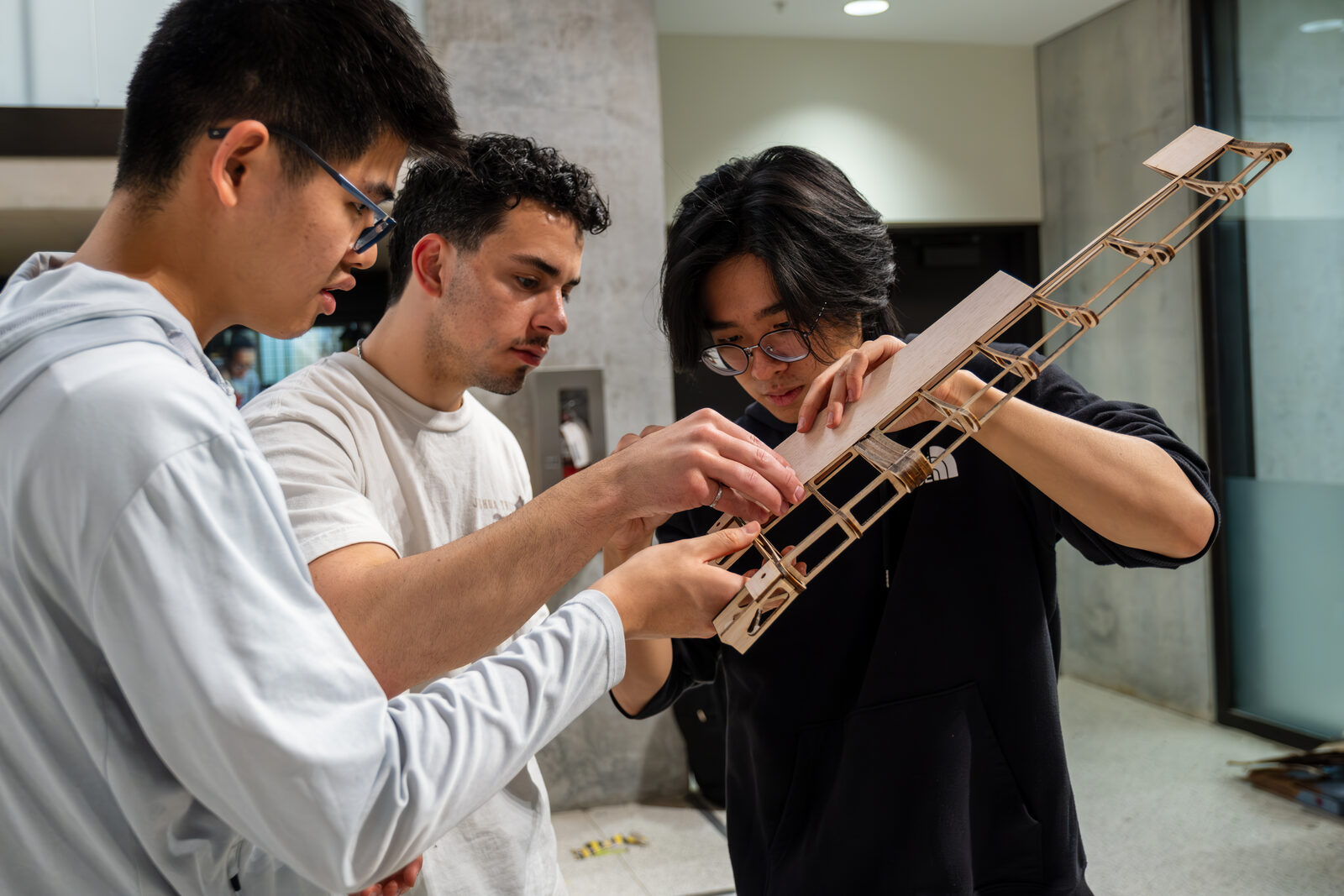
Through two design–build–fly cycles, the analysis choices showed up in assembly and flight behaviour. Some trades held; others moved.
What carried forward from that loop, beyond the planform numbers, was the habit of keeping both physics in the same iteration. The interface between aero and structures is where the trade-offs actually show up; running them separately hides the part of the design that matters.
What I’d do differently
Earlier engagement with manufacturing. The cleanest aero choice is not the right one if the build schedule cannot absorb it, and I would now spend the first design week in the shop with the structures and build leads before the first lifting-line run.