What this is
UTIAS AER1216 Fundamentals of UAVs is the introductory UAV systems course — fixed-wing track on one side, multirotor track on the other, paired with three problem-set assignments and a design project. This page is the fixed-wing half: an airfoil pick, drag-polar generation, planform geometry, and the constraint-driven sizing pass that lands a single design point.
The course frame is the textbook chain — airfoil → polar → planform → constraint → sizing — done end-to-end on one set of mission requirements. Nothing here is novel. The point is that every choice has a chart it has to live on, and every chart points at the next one.
Aero design — airfoil, planform, polar
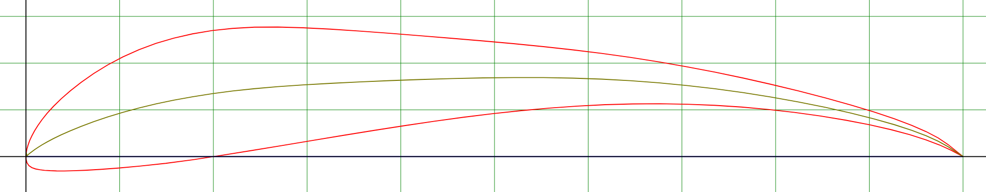
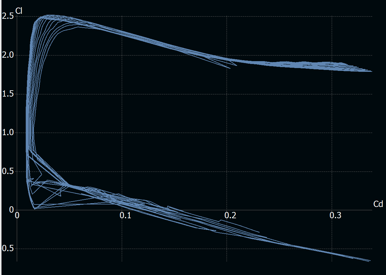
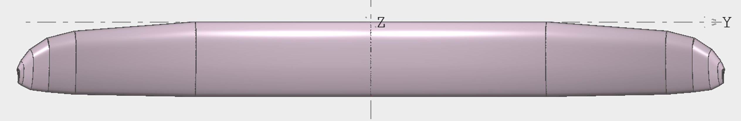
The airfoil pick is the Selig 1223. High-camber, high-lift, well-characterized in the public databases, and the right shape for a low-Re, high-CL fixed-wing UAV; the section outline is the first figure on the page. The polar is generated in XFLR5 — Cl–Cd over the angle-of-attack range — and reads as the standard drag-bucket diagnostic the polar is supposed to be: a clean low-drag region between the lower-surface and upper-surface separation knees. The planform top-down view is the geometry the polar sits inside, taken from the wing CAD.
Together these three figures are the aero side of the design done at the level of artefacts a constraint-and-sizing pass can consume.
Performance analysis
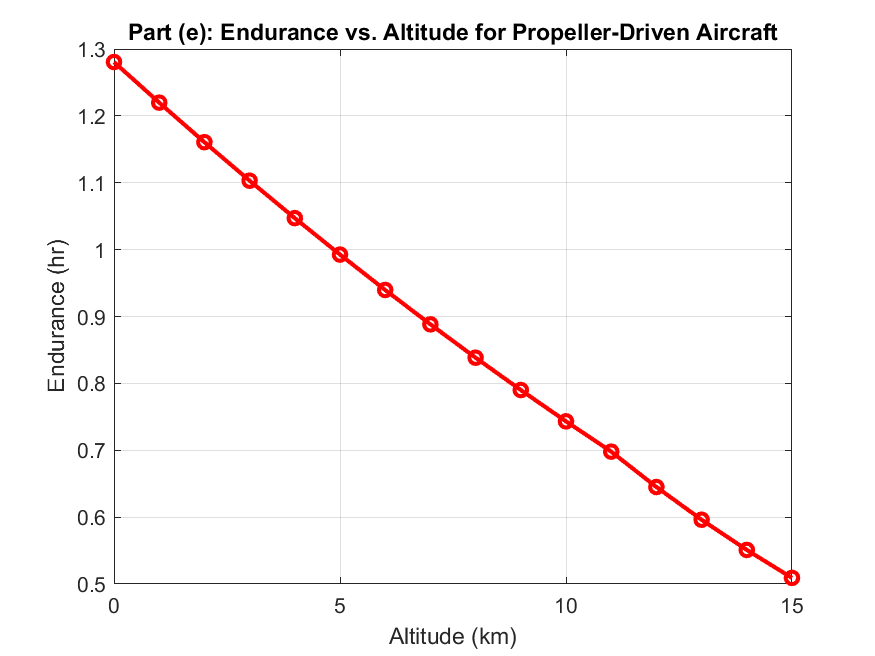
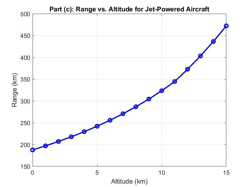
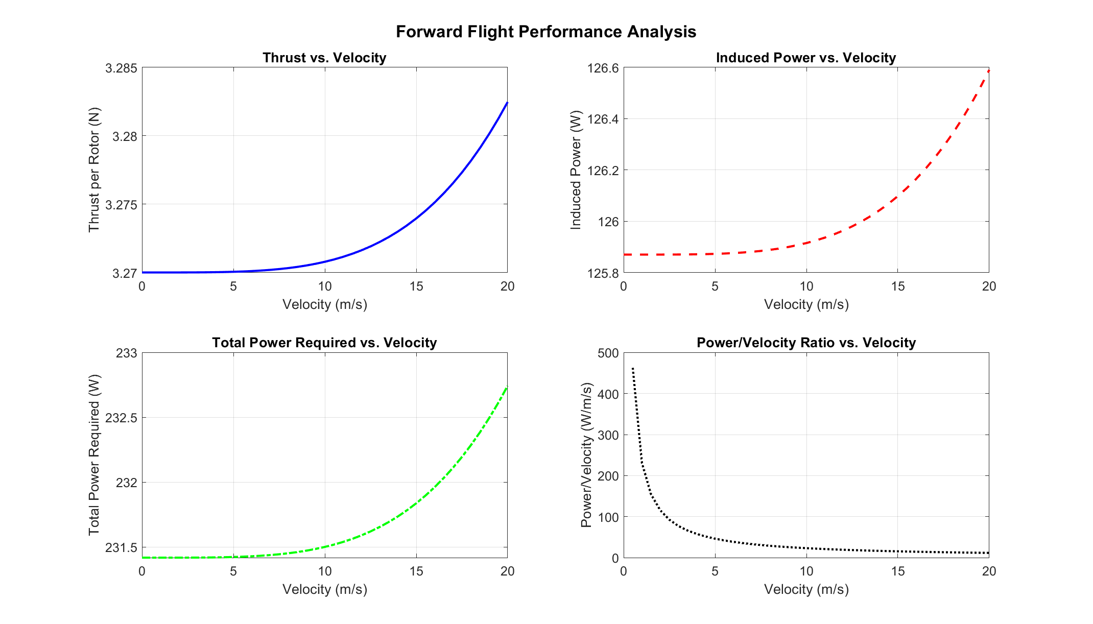
The assignment-grade plots are the next layer down, generated against altitude on the same airframe assumptions: endurance vs altitude (where the design wants to live for a long mission), range vs altitude (how far it can go on the same fuel/charge), and the forward-flight performance figure that ties power-required and power-available into the velocity-vs-altitude envelope. These are the kind of figures every introductory UAV course produces; what they earn here is the consistency check — the design point on the constraint diagram has to be inside the envelope these plots draw.
Constraint analysis and the design point
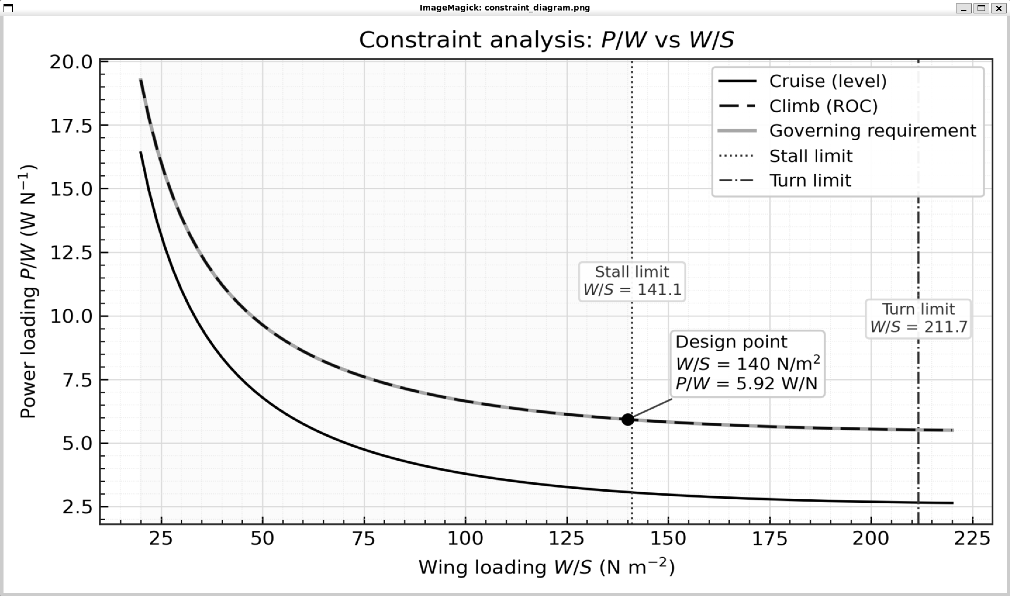
The hero figure is the constraint diagram in P/W vs W/S — the textbook formulation. Cruise (level flight), climb (rate-of-climb requirement), and the turn-limit and stall-limit lines bound the feasible region; the governing requirement is whichever line is most restrictive at each W/S. The design point lands at W/S = 140 N/m², P/W = 5.92 W/N — inside the feasible region, with margin against the closest bounding line. That single point is the answer the chain of figures was set up to produce.
What it earns
The Fundamentals course is not where novel UAV design happens; it is where the design vocabulary gets internalized. By the end of the page the airfoil pick, the polar, the planform, the performance envelope, and the constraint-driven design point form one connected chain — the kind of chain that lets a heavier downstream design pass start at “we know what each chart wants from the others” rather than “we have an airfoil and what now”. The work is course-grade by construction; the discipline of completing the chain is what carries.