University of Toronto Aerospace Team · SAE Aero Design · Minerva 2024, Stratus 2025 · wing aerodynamics
The climb angle was free over a quarter of a degree where the file meant fifteen, and that bound is what chose the aerofoil.
A competition wing described by twelve numbers and scored on one: the largest payload the aircraft can lift, which the project measures with a surrogate rather than with payload itself. Judged as sections, one of the two aerofoils is better at every Reynolds number this wing sees. The run picked the other, by 2.8 kg of that surrogate. Re-implementing the loop in Python to check it found the reason: OptimizerMain.m converts an angle that is already in radians, so the climb angle was bounded 57 times tighter than the file intended. Under the corrected bound the two sections do not separate.

How big the wing has to be
Before any shape is chosenSAE Aero Design gives a student team a season, a rulebook and a field. The aircraft has to leave the ground inside a marked distance, fly a circuit and land, and the score is how much payload it carried. UTAT enters the Advanced Class. The wing is one part of that aircraft, and the first question about a wing is not what shape it should be. It is how big.
There is a plain way to answer that. Choose a wing area. Work out the heaviest aircraft that area could still get off the ground in the runway available, the heaviest it could still hold the required climb with, and the heaviest it could still fly the required turn with. Whichever of the three is smallest is what an aircraft with that wing is allowed to weigh. Then do it again for every area. The curves that come out are the wing's whole story before a single aerofoil has been named.
Four numbers come from the rules and the field. The take-off has to finish inside 146 m, which is the Fort Worth field as measured off a map. The climb has to hold ten degrees. The turn has to hold fifty degrees of bank. The motor has 750 W. A fifth constrains the answer from the side: span may not exceed 3.048 m, which is 120 inches, and once an aspect ratio is chosen that span limit becomes a limit on area.
The calculation is the team's. constraintAnalysis.m and its component drag build-up were written between 2021 and 2022 by Neil Farvolden, Daniel MacGregor and Adele Crete-Laurence, and the propeller efficiency is read from the team's own lookup table for the 22x12. Both files were ported to Python line for line, approximations included, and the port was checked against the figure they committed. Seven quantities can be read off that plot and the worst disagreement is .
Sizing the wing
01 Three ways to be too heavy
Take-off first, because it is the one with a tape measure on it. At each wing area, the heaviest aircraft that still leaves the ground inside 146 m. More wing lifts sooner, so this line rises, and it rises fast enough that take-off is never what stops this aeroplane. Climb is harsher. Holding ten degrees means carrying the aircraft's own weight uphill on 750 W, and the propeller gives less help the slower it goes, so the line rises slowly and stays low.
02 The one that binds
The turn asks for lift, not thrust: fifty degrees of bank multiplies the lift the wing has to make by about 1.6, and a bigger wing pays that bill more easily. It sits above climb everywhere on this sweep. An aircraft has to satisfy all three at once, so what it can weigh is the lowest line at each area. That envelope is the climb line, from end to end. Climb is what sizes this aeroplane, and take-off, the requirement with a number in the rulebook, is nowhere near binding.
03 Where it stops
The envelope keeps rising, so the design point is wherever the sweep is made to stop, and what stops it is the rulebook: 3.048 m of span at this aspect ratio is of area, and the answer sits on that line. Which is worth being suspicious of. Nothing in these three curves charges anything for a bigger wing: there is no structural mass in the model at all, and the team's own README lists adding one as work still to do. A calculation that gets wing area for free will always ask for the maximum, and this one does.
The wing optimiser supplies that missing cost. It minimises take-off mass less the mass of the spar that holds the wing up, so a wing that buys lift by growing pays for it in the same number it is scored on. The sizing above and the optimisation below are not the same aircraft: the constraint analysis is the team's competition sizing at aspect ratio 6.13 and 1.516 m², and the loop below runs on the case the archived optim_vars.mat holds, 2.000 m² at aspect ratio 4.645. What carries across is the question, not the numbers. The sizing says where an area and an aspect ratio come from; the chapter below takes one such pair and asks what shape to make of it.
Moving either slider recomputes nothing in the browser. Every curve here was solved by the ported calculation before the page was built, on the ten wing areas their script sweeps. Two things are held fixed while you move them: the stall margin, at the 1.15 both of their scripts use, and the aerofoil's two drag constants, at the values in the case they committed. So the sliders ask what a different wing shape would do, not what a different aerofoil would do.
Twelve numbers, and one number to judge them by
What was being designedSAE Aero Design scores payload, so the wing's job is to let the aircraft take off heavier. That single objective is what makes the problem tractable and it is also what makes it a trap: every discipline can improve its own number while the aircraft gets worse. The team's answer was to stop scoring disciplines and score the aircraft.
The objective the optimiser minimised is -(mtom - m_spar): the largest take-off mass the mission allows, minus the mass of the half-wing spar, both in kilograms. The project's own README calls it a surrogate for payload.
The wing itself is four spanwise stations at a fixed 3.048 m span, which is 120 inches and is not a variable. Each station carries a chord and an incidence; the wing carries an area; and three of the four flight conditions carry an angle of attack. That is the twelve. Two are frozen at the root, which fixes the reference the other chords and incidences are measured against, and the chords are constrained to fall monotonically outboard so the optimiser cannot return a planform nobody would build.
One evaluation, all the way through
The loopFive hundred times, the optimiser handed twelve numbers to a function and got one back. This is that function, run on the twelve numbers it settled on, with every quantity taken from the arrays it produced. The cards are in call order and the arrows between them are the arguments the code passes: the aerodynamics feeds the spar because sizeSpar takes the lift and moment distributions as arguments, and nothing feeds back, because this loop has no aeroelastic iteration in it.
The framework is the team's, written in 2021 by Neil Farvolden, Andrew Ilersich and Adele Crete-Laurence. What is being shown here is one 2024 run of it and what that run decided. MATLAB was not available, so the modules were ported to Python and the port was checked against what the MATLAB wrote: the bending moment to 9e-15 relative, the deflection to 5e-18 m, and the objective to its last digit.
The evaluation
01 The wing
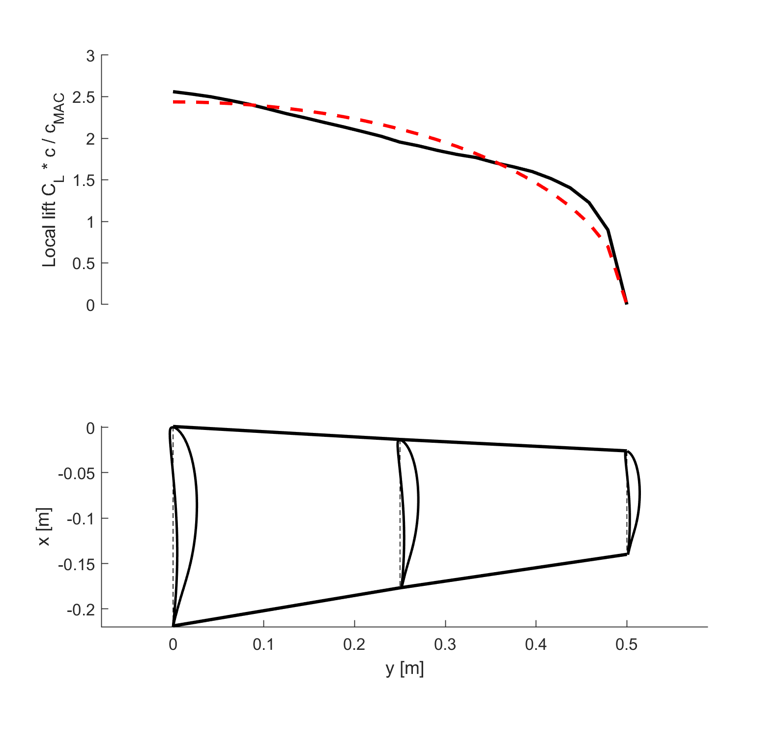
Four chords and four incidences, scaled to the area asked for. The chord holds to a third of the half-span, then two thirds of it goes outboard. The lifting line iterates on circulation across 49 stations until it stops moving. Close to elliptical inboard, shedding load early at the tip: what the taper buys.
02 The structure
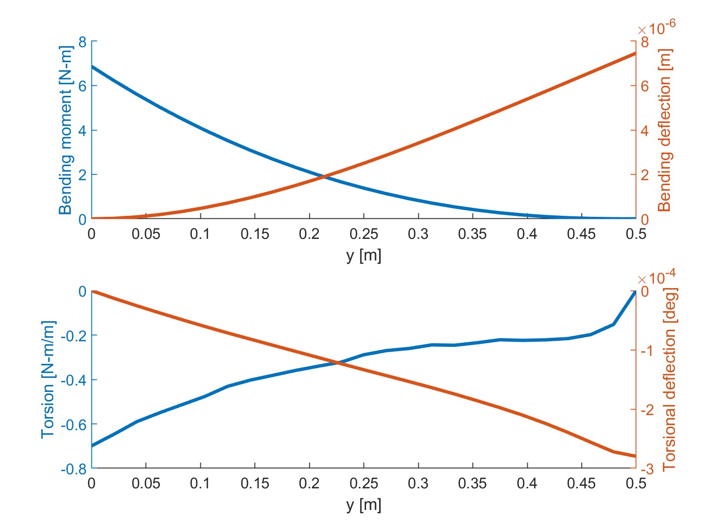
Integrate that load twice from the tip in, apply the 3.3 load factor: 326 N m at the root. The tip bends 9.3 mm against a 152 mm limit. Bending is not what sizes this spar. Twist is. The section's pitching moment runs the whole span, and in the turn the tip goes past its two degree limit before the spar is stiff enough.
03 The aircraft
Parasite drag is a component build-up, done once at stall speed. Induced drag comes from the lifting line. The tail's share arrives last: a nose-down moment has to be trimmed. Four flight conditions, four allowable masses, and the aircraft is the smallest of them. Climb-out, and not close: the next constraint would allow 39 % more.
The more efficient section loses, until the box is right
Choosing the aerofoilThirty-one aerofoils were run through the whole loop and nine went to a shortlist. Two of them survive as machine-readable tables, complete with the XFOIL polars the run used, so those two are the ones compared here.
Judged as sections, it is not close. FX76MP120 has the better lift-to-drag ratio at every Reynolds number the wing sees and a smaller nose-down pitching moment. Judged on the aircraft, with the same planform, the same mission and the same spar sweep, it loses 2.8 kg of payload surrogate. A decision matrix scoring efficiency and pitching moment would have picked it. That is what the run found, and it is the first half of the answer.
The second half came out of checking it. The optimiser was allowed to choose an angle of attack for the climb, and OptimizerMain.m converts that bound from degrees to radians twice, so the angle was free over 0.26 degrees where the file meant 15. That box is not neutral between two aerofoils. The section with the lower maximum lift coefficient needs more angle to make the same climb lift, and the bound is exactly what it needed. Below is the same comparison run at every ceiling from 0 to 15 degrees.
The spar is sized by twist, in the turn
StructureThe spar is not optimised. It is swept: six cap widths by six cap thicknesses, each one integrated for bending deflection and for torsional twist under that flight condition's own loading, and the lightest one that stays inside both limits is charged to the objective. A candidate that misses a limit is not rejected, it is charged a penalty, which is how a hard requirement is turned into something an optimiser can walk down.
Five hundred evaluations, and where they stopped
The searchMATLAB's surrogateopt was given a budget of 500 evaluations and used all of it; it stopped because the budget ran out, not because it converged. The run kept one objective value and one constraint violation per evaluation. Everything that produced them was discarded.
Re-running the whole history through the ported loop recovers the rest: which flight condition bound each candidate, and whether its spar sweep was penalised. It is also five hundred independent checks on the port instead of one.
The wing was built and the aircraft flew
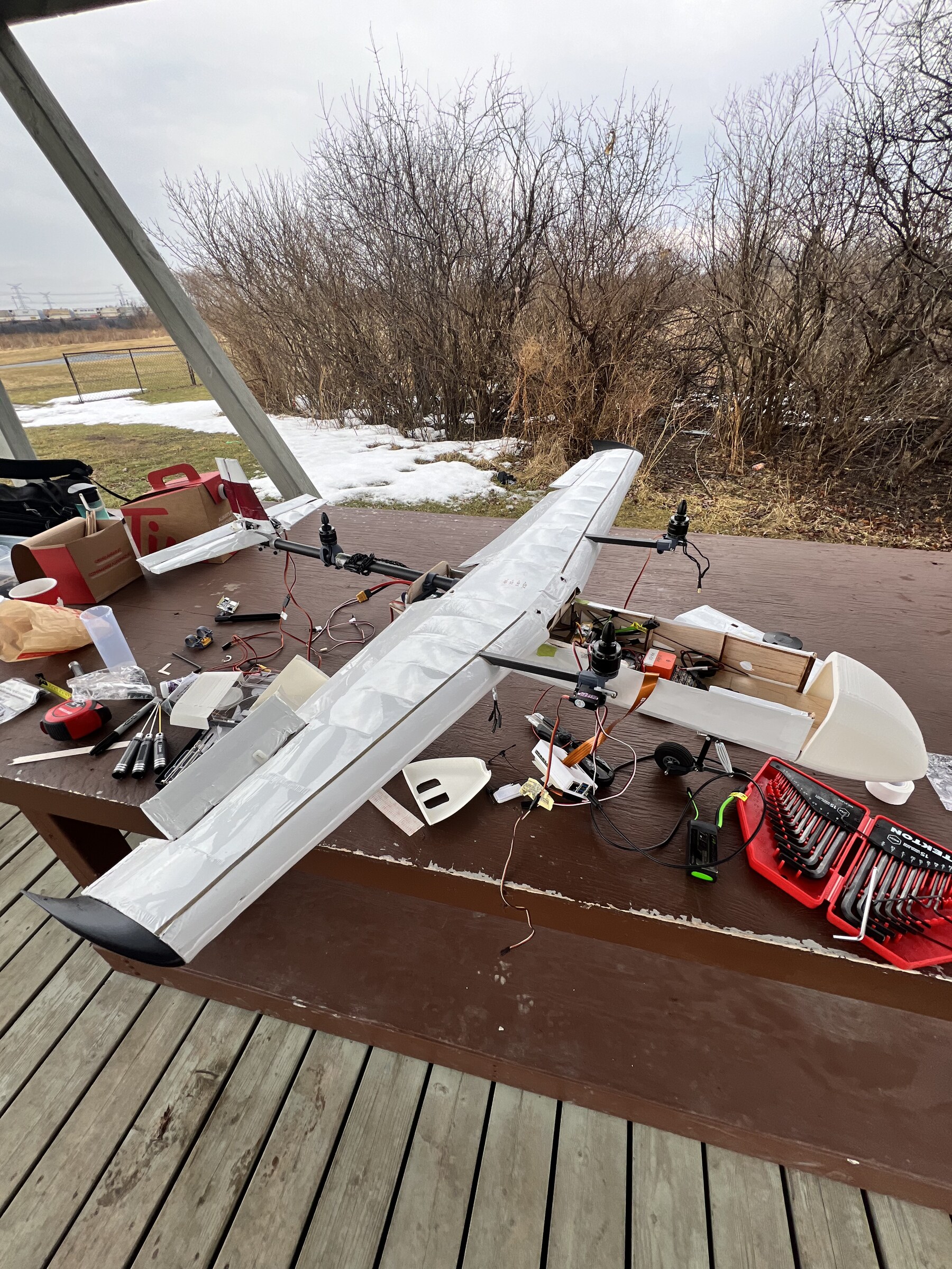
Design, build, flyThe chord distribution above is a stack of laser-cut ribs, the spar caps are carbon over foam, and two airframes, a season apart, each went to competition. A wing that exists is the strongest available statement that the numbers were used.
The aircraft, and the parts it was cut from
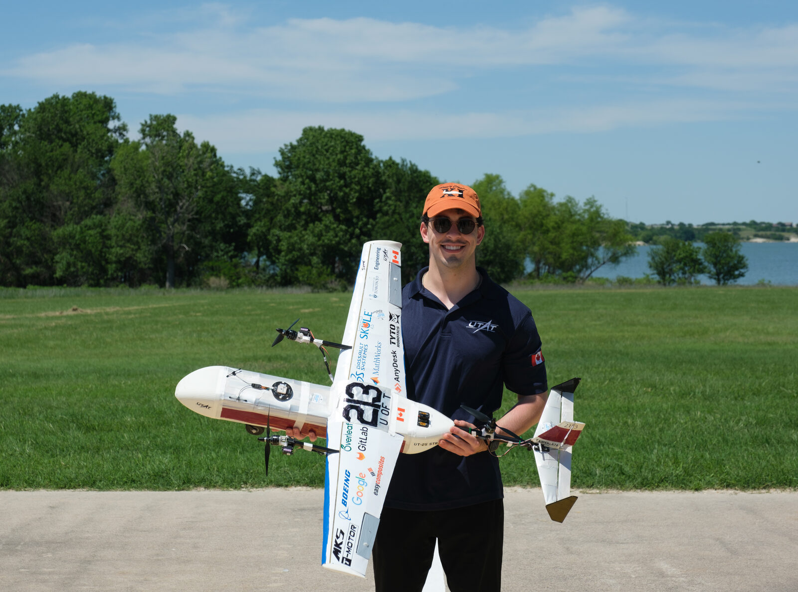
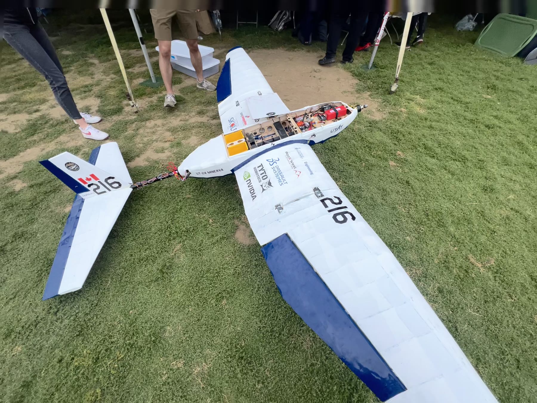
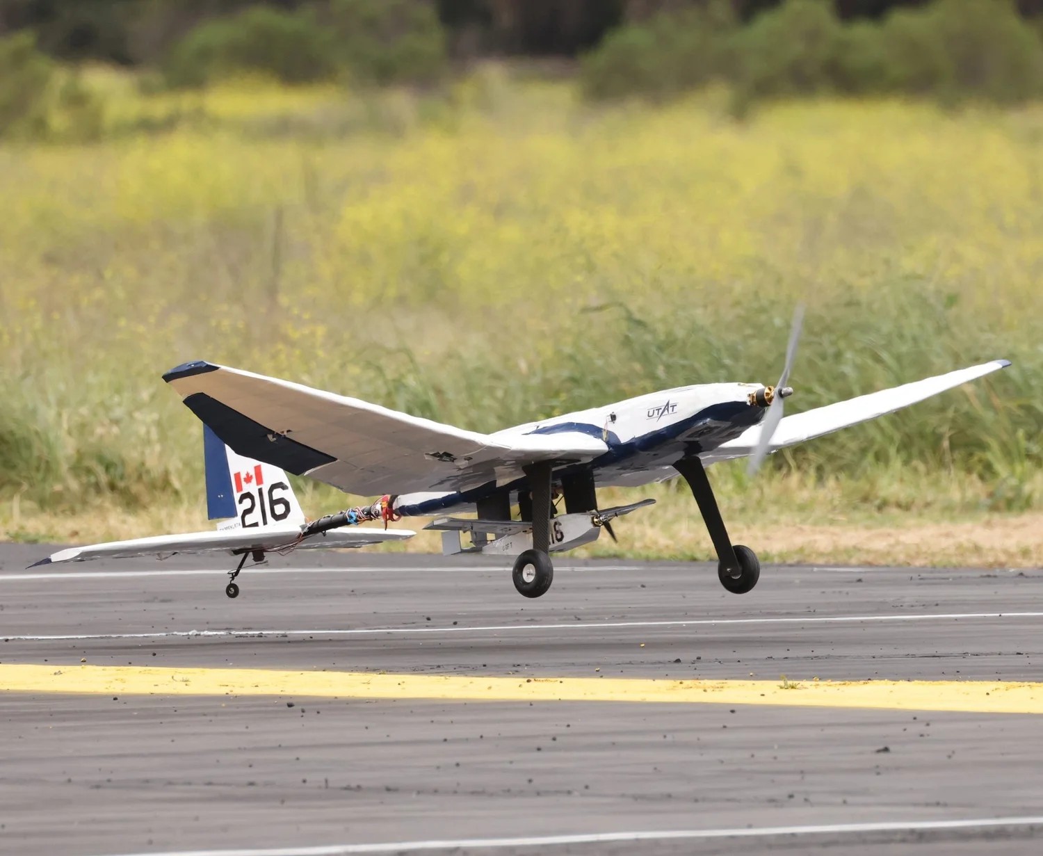
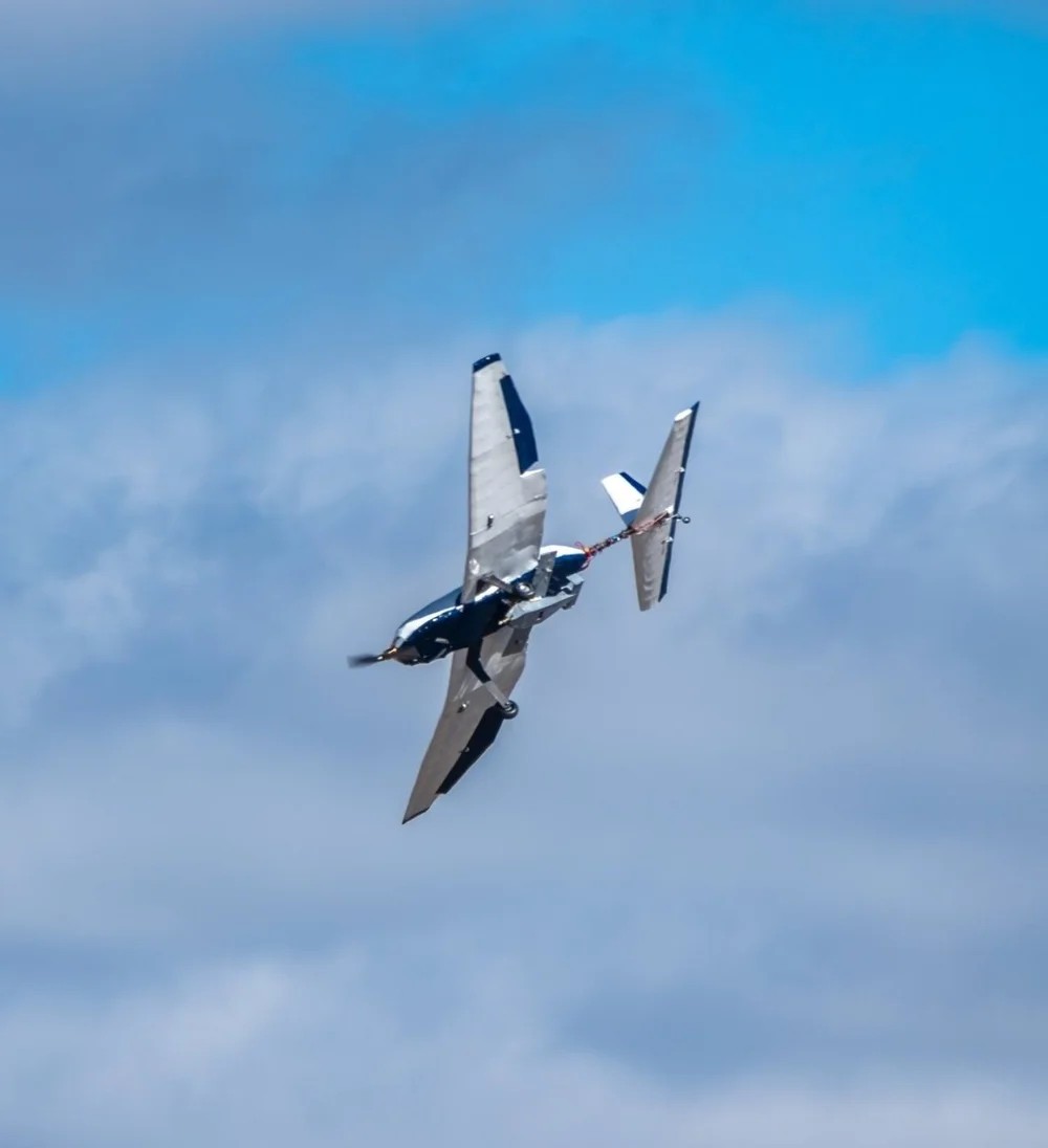
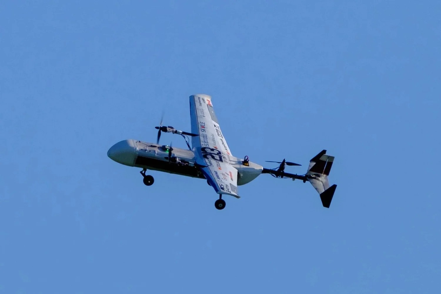
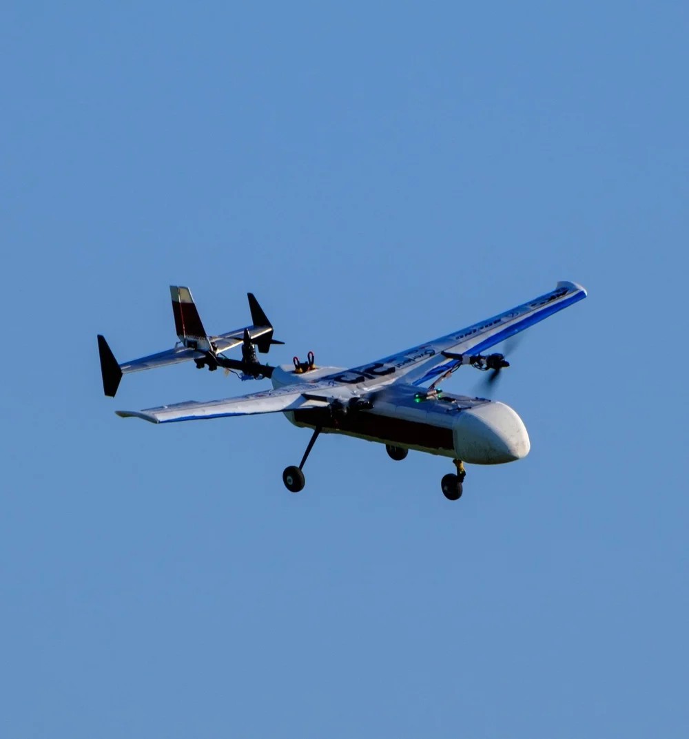
Everything above is an optimiser talking to itself. These are what came out the other end. Two airframes, two seasons: UT-24 Minerva at SAE Aero Design West 2024, and UT-25 Stratus, the one this loop sized, at SAE Aero Design East 2025.
The two airframes in the air
Photographed by the team at the two competitions. Everything above ends in a chord distribution and a spar cap thickness. This is the same wing at the condition it was sized for.
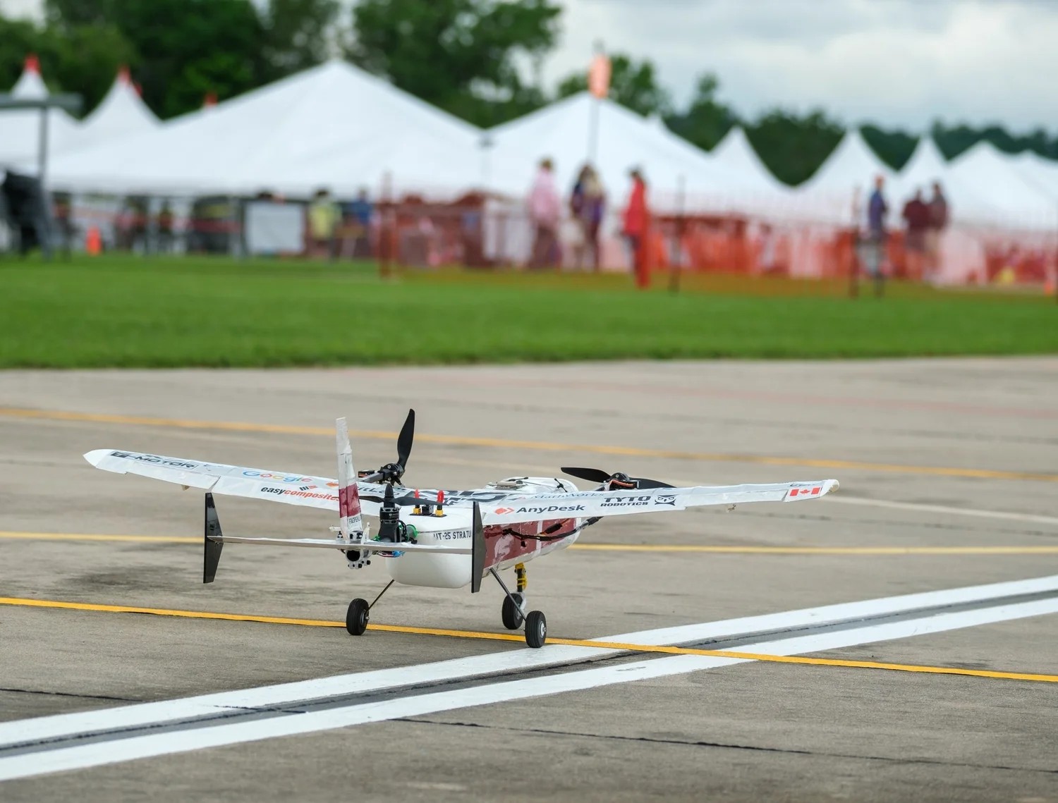
The two mission patches
The team draws one per season. They are the shortest statement anyone on it makes of what the aircraft was built to do, and both of them describe a payload rather than an aeroplane.


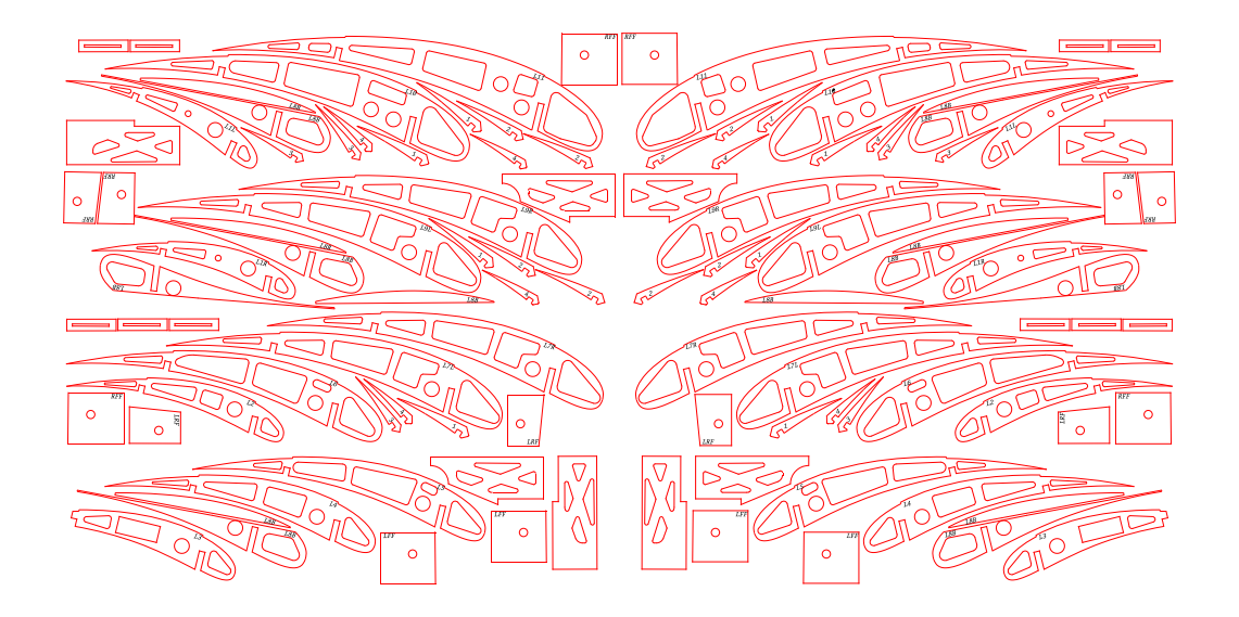
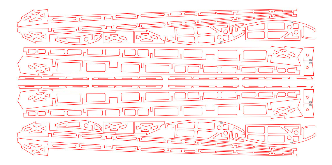
The cut sheets
The optimiser's output is a set of numbers. What a laser cutter needs is a nested sheet, and the translation between them is where a geometry either survives manufacture or does not.
What I would do differently
Earlier engagement with manufacturing. The cleanest aerodynamic choice is not the right one if the build schedule cannot absorb it, and I would now spend the first design week in the shop with the structures and build leads before the first lifting-line run. The cut sheets above are why: every rib on them is the consequence of a number chosen weeks earlier by someone looking at a drag polar.