About
Numerical methods on one side, airframes that had to fly on the other.
Aerospace and mechanical engineer, in the Alberta foothills. The two threads run through everything below, along with the tooling and the machines both of them run on.
- Now
- CFD reinforcement-learning researcher at Alignerr, on contract since July 2026. I author the reference solution an attempt is scored against, then test the scoring itself with controlled CFD studies, so the reward follows the physics rather than the solver's noise.
- Trained
- MEng at the University of Toronto Institute for Aerospace Studies, UTIAS, completed summer 2025, supervised by Prof. David W. Zingg. BESc in Mechanical and Materials Engineering, Western University, 2019 to 2023.
- Open to
- Engineering roles across simulation and analysis, engineering software and systems, verification, and design that ends in hardware. Aerospace especially, and any technically demanding field. Calgary preferred, on-site or hybrid anywhere in Canada, and open to remote work.
Seven capabilities, and the stages that moved them
How the capability developedThe columns are the stages of a life and an education. A line gets heavier in the stage that moved that capability up a rung: introduced, developed, deepened, applied and integrated.
Mathematics and computation numerics · solvers · scientific software · the machines they run on
Design and machines CAD · finite elements · structures · thermal · materials selection
Research verification and validation · experiment design
Aviation and flight formation operations · safety culture · flight dynamics · uncrewed aircraft
Making and building fabrication · shop · embedded control · full-stack delivery
Recording the work imaging · film · technical writing
Leading and handing over coordination · design review · mentoring · reports · analyses another engineer can re-run
Where two became one piece of work
Where two became one piece of work
Where two became one piece of work
Where two became one piece of work
introduced developed deepened applied and integrated a start before any year shown two capabilities, one piece of work
Strathcona-Tweedsmuir School · 2007 to 2019
Aviation, flight and operations
phase introduced → developed
Participation in the Mooney Caravan to EAA AirVenture Oshkosh, as recurring volunteer work inside that community: filming and editing is one part, and by the end of this period it has also meant formation preparation, briefings, and the operating discipline underneath them.
Hobby radio-control flying, largely on the simulator, plus full-scale involvement. This is not a claim of solo full-scale flight. Formation training is current; no flight-training milestone is dated here.
One measurement, in full
Wall y⁺, over a runThe slow thing to learn was not how to run a solver. It was how to find out whether a result is entitled to the model that produced it. This is the figure that settles that question for an external aerodynamics run, with the conditions it was taken under.
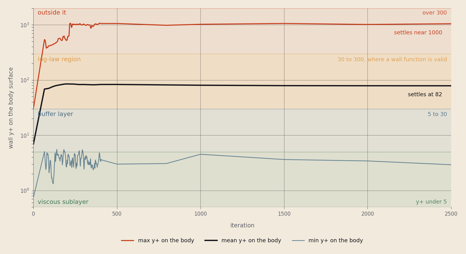
Ahmed body, k-ω SST with wall functions. Maximum, mean and minimum wall y⁺ over the body surface, for the length of the run, against the four regimes the closure is defined on.
Wall y⁺ is how far the first cell centre stands off the surface, measured in the units the turbulence closure is written in. A wall function assumes that distance lands between 30 and 300. Over the last hundred samples of the archived baseline run (Cd 0.2253) the body mean settles at 82, inside that band. The maximum settles near 1000, and is outside the band for 99.7 per cent of the samples. The minimum is down in the viscous sublayer.
Three decades of y⁺ on one surface at one instant. Log axis, because the regimes are defined on it.
Limits
- The mesh is in the wall-function regime. It is not resolved to the wall anywhere.
- The mean being inside the band is not the same as the body being inside it. Somewhere on that surface the first cell is in the sublayer and somewhere it is three decades away, at the same moment.
- It says nothing about whether the drag number is correct, and it is not a comparison against published results for this body.
Roles
And what came of each-
Reinforcement-learning environments grounded in CFD
AlignerrCFD RL researcher · contract, remoteJul 2026 →
An environment, here, is a fluid-dynamics problem turned into something a model can attempt and be scored on: a flow case, a solver behind it, and a reward that has to come out the same way every time it is run. Building one is four stages. The flow case has to be technically valid. The reference solution it is scored against has to be right, which means solving the case properly and being able to say why the answer is the answer. The score has to be the same number every time the case is run. And the scoring itself has to be audited.
The audit is where the engineering goes. A reward that climbs because a solver went unstable in a convenient direction is worse than no reward at all, and so is one that a shortcut can game. Separating a genuine improvement from numerical noise means running controlled studies on the scoring itself: what counts as a correct flow solution, and how do you defend that against a discretisation that is quietly wrong.
What the work isFlow-case setup · reference solutions · reward behaviour · controlled studies on the scoring itself
OngoingVerification, in a setting where the thing being verified is not the solver but the number the solver is being used to award.
Limit The tasks themselves are proprietary and are not described here.
Same question, on this site CFDLab builds three solvers for one problem and checks each against an exact answer; aeroBASE is the same discipline applied to the case files rather than to the solver.
What one task is made of. The same check, in two places. A solver is checked against an answer known on paper; a model is checked against an answer written for the case, which is the part this role adds. -
Analyses another engineer can re-run
Sepal AIaerospace engineer · contractNov 2025 – Mar 2026
Aerospace studies and computational tools for small uncrewed aircraft, taken from a technical request to a self-contained analysis that supports an early design decision. The largest was a multirotor mission-planning model: vehicle and operational assumptions in, mission time and battery energy margin out, so that a concept could be checked against the mission it is supposed to fly before anything is committed. It was accepted following review.
Beside it, first-pass tools for fixed-wing constraint analysis and for propulsion trade studies. Constraint analysis is the same object as in the UTAT wing work: sweep the wing area, find the heaviest aircraft each requirement still allows, and read the design point off the lowest curve.
The requirement that shaped all of it was reproducibility. Every task documented the path from assumptions to result, so another engineer with none of the original setup could review it and get the same answer. That is a harder property than producing the answer, and it is the one that decides whether an analysis is worth anything a month later.
What the work isMission-planning model · fixed-wing constraint analysis · propulsion trade studies · reproducible hand-off
ProducedA mission-planning model accepted after review, and two first-pass sizing tools. Delivered as reproducible analyses.
Limit No wider aircraft programme.
The same objects, worked out here UTAT's first chapter is a constraint analysis end to end, ported and checked against the figure the team committed; UAV Fundamentals is a sizing loop that has to close on itself before it can size anything.
What an early sizing decision looks like. The design point sits on the lowest curve, because a size is whichever requirement allows the least. The numbers are UTAT's, because those can be published; Sepal's own studies are the client's. What the largest piece of work answered. Assumptions about the vehicle and the operation go in; how long it can stay up and how much energy is left over come out, and the second one is the answer that decides.
Two years on a student team
2023 to 2025, alongside the MEng-
Two airframes, two design cycles
UTAT SAE Aeroaerodynamics contributor, then aerodynamics lead2023 – 2025
Wing aerodynamics on Minerva in year one and the Stratus tiltrotor in year two: nonlinear lifting line on the aero side, beam-bending spar sizing on the structural side, and an MDO loop tying the two to the competition's payload objective. Aerofoil choice had to survive balsa and ply tolerances, and the planform had to clear the trailing-edge robustness check before it cleared the lift-distribution one.
In year one I was the main aerodynamics contributor on Minerva. In year two, after a mission overhaul, I led aerodynamics for Stratus, coordinated the subteam and reviewed analyses with junior members. Decisions went through design reviews with structures and manufacturing and came out as geometry the team could build and fly, and I laser-cut and covered wings alongside the people who built the rest.
What the work isNonlinear lifting line · beam-bending spar sizing · MDO loop on the payload objective · trailing-edge robustness check
OutcomeTwo first places in the Advanced Class design report: Minerva at SAE Aero Design West 2024, Stratus at SAE Aero Design East 2025, Fort Worth. Wing aerodynamics owns part of that report on both airframes.
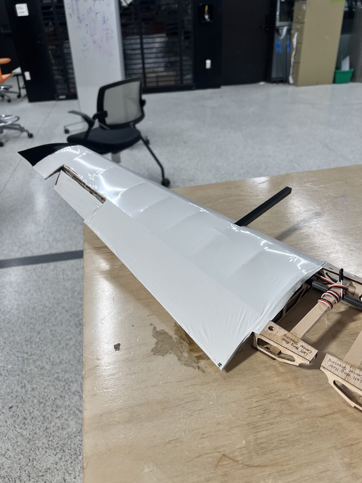
The wing on the bench, covered, with the linkage in at the root. 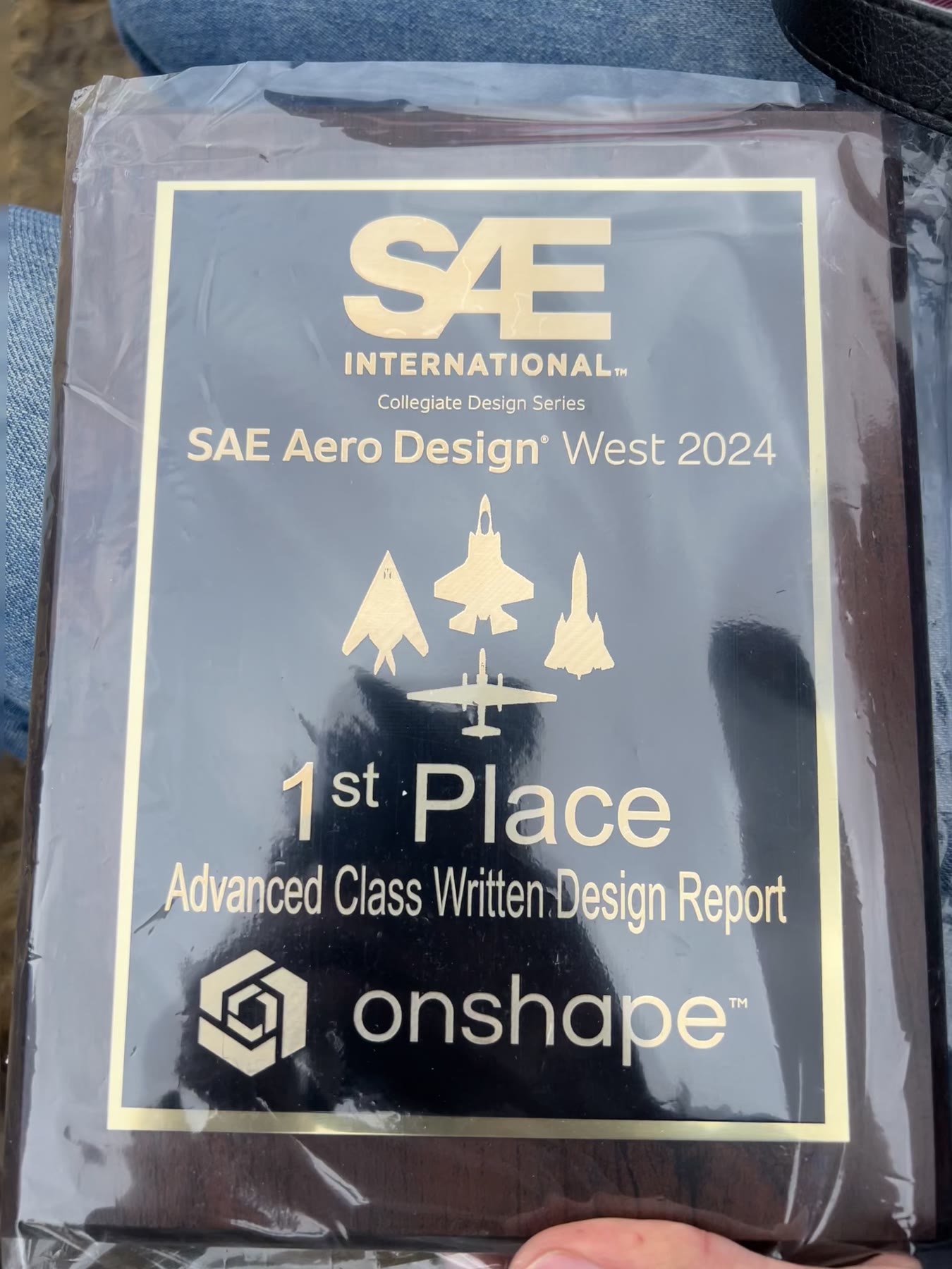
SAE Aero Design West 20241st Place · Advanced Class · Written Design ReportMinerva, year one 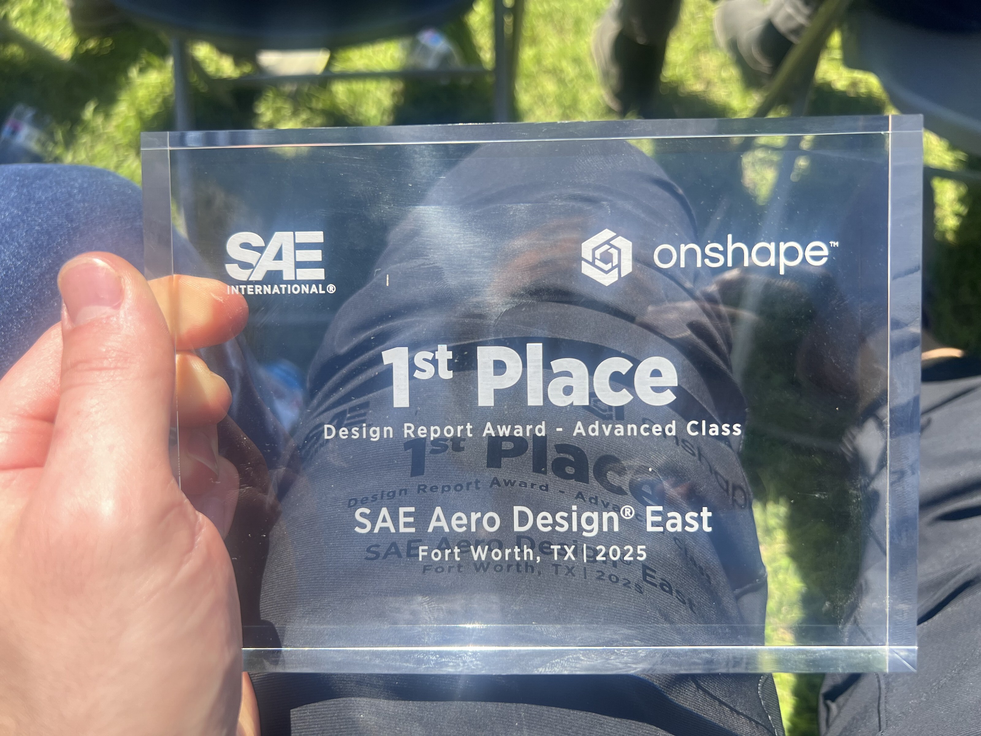
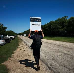
SAE Aero Design East 20251st Place · Design Report Award · Advanced Class · Fort WorthStratus, year two
An aircraft, a solar car and a sailing rig
2022 to 2023, before the MEng-
Structural CAD for an experimental STOL
Mountaineer Aircraft Ltd.CAD engineerApr – Aug 2023
On site in Squamish: SolidWorks structural components for an experimental STOL platform, iterated next to the fabrication bench so each part made the trip from screen to fixture with its tolerances intact.
OutcomeParts that were built. Flown in the airframe, including a sandbar landing. The shop continues the Murphy Radical lineage.
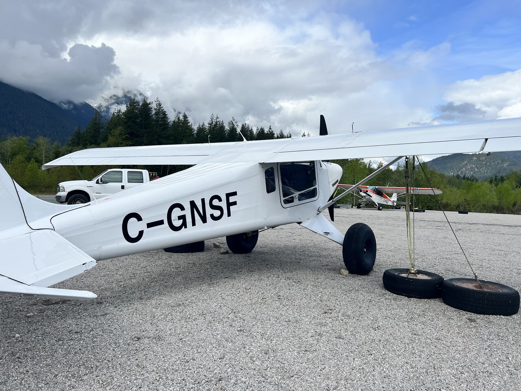
C-GNSF at Squamish: the airframe the parts went into. Sandbar landing, Squamish: the airframe at touchdown, with parts from the bench on it. -
Solar-car chassis, redesigned in FEA
SunstangCAE design engineerSep 2022 – Apr 2023
Tubular-frame chassis redesign in SolidWorks with FEA, run alongside the aero and electrical sub-teams so array mounting and packaging stayed compatible with the structural target.
ProducedA chassis design carried by a team with two other sub-teams' constraints attached to it, which is the part that makes it engineering rather than analysis.
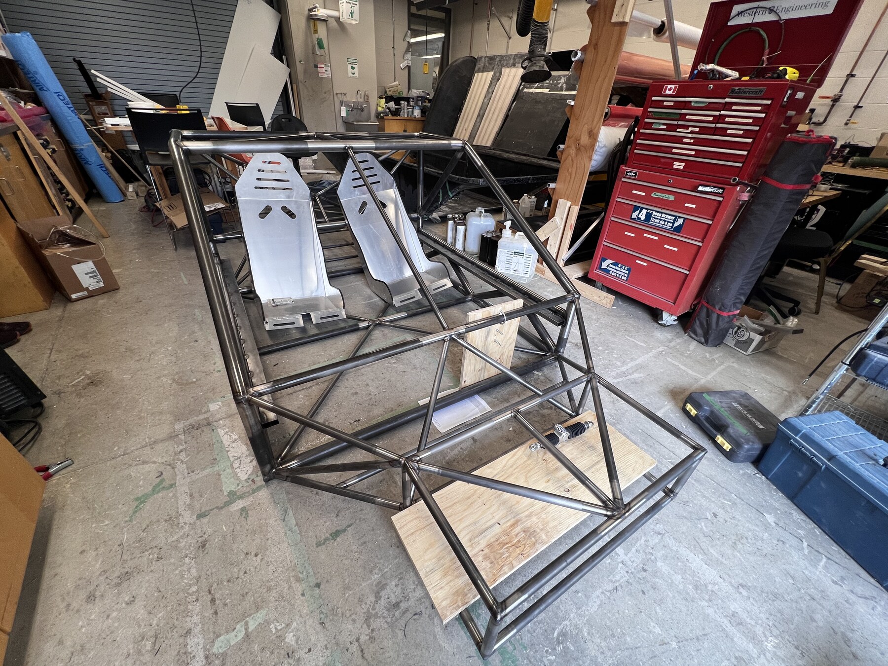
Sunstang: tubular chassis, mid-build. -
Docking assist for a solo sailor
Western capstonesimulation leadSep 2022 – Apr 2023
A docking-assist system for one person in a confined finger-dock marina, designed to stay usable across a range of wind and current. As simulation lead: the dynamic model, boat plus docking mechanism in the loop.
ProducedCAD on the mechanism, a prototype, and a design report.
Dated, grouped by period
TrajectoryI grew up around airframes, close enough to learn that a mechanical system tells you what it is if you read it carefully. The maths came later, when "the airframe flies that way" stopped being enough of an answer.
Since then a degree, a competition team and an independent project have usually been running at the same time, so the rows below overlap.
Piano, teardowns, repositories, and what is next
Outside the bench
RCM piano and oboe from before any of the engineering. Still at the piano, always listening. Engine teardowns, ignition resets and borescopes, on an N54 and on an aircraft engine when one is open. Pilot training in progress. The espresso machine is its own small control problem, and so, on a bad afternoon, is .
Where the code is
Most of the repositories are private, which is why the evidence is shown in place rather than linked. CFDLab and the machines it runs on are where the numerics continue.
What is next
Aerospace, automotive and energy for preference. I work end to end, mesher through solver and post-processing to the machine it runs on, and the method side is where I want more time: SBP and SAT boundary closures, discontinuous Galerkin, finite volume, and the DNS, LES and RANS end of turbulence.
What is on
Monthly mixes, kept since 2018. The titles are the year and a Roman numeral.


↑ and ↓ set ν. Reach the outlet in as few steps as you can, with the pulse still a pulse.
Linear advection, explicit first-order upwind: uj ← uj − ν(uj − uj−1). Stable for ν ≤ 1, and at ν exactly 1 it is an exact shift, so the fastest and the most accurate setting is the one on the edge of the cliff. Under reduced motion nothing moves on its own: → takes one step.
The same question on a scheme that ships: CFDLab chapter 06 marches this with the five-stage scheme and implicit residual smoothing, where the ceiling moves with the smoothing coefficient and the edge of the cliff stops being the fastest clean setting.