Public · Apache-2.0 · Tesseract Hackathon 2026, Track 02
A wing designed as if it were rigid lands 16.2 % worse, and four cheap ways to see that coming all fail.
A flexible wing twists under the lift it makes, and the twist changes the lift. Designing one from the rigid wing's gradient is normal practice and usually fine. This measures where it stops being fine, and asks whether anything cheap can tell you in advance.
What is being designed, and what is allowed to move
The objectOne wing, held at a fixed trimmed lift. Six numbers set its built-in twist and its torsional stiffness along the span, and the objective is induced drag plus a structural mass proxy. Nothing else about the wing changes.
Two knobs, 289 wings
The sweep varies two of the six: tip geometric twist from −0.10 to +0.06 rad, and a uniform stiffness multiplier from 10+0.6 down to 10−1.0 times the design value, seventeen values each. One cell of the map further down is one wing, solved to convergence, with both gradients computed at it.
What makes a design bad
Two things, and only one of them is a hard stop. Torsional stiffness has a lower box bound, and both optimisation runs drive straight into it. Below that bound sits divergence, the dynamic pressure at which the aerodynamic stiffness cancels the structural stiffness and the twist grows without limit; the design condition here sits at 74.7 % of it, against 37.1 % at the starting design. A box bound stops the optimiser, not a stability constraint.
Why coupling is the whole difficulty
The lift twists the wing, and the twist changes the lift. Solving it means running the aerodynamics and the structure against each other until they agree, then transposing that whole loop to get a derivative. The rigid gradient skips it: it is the exact derivative of the rigid wing's objective, it is correct in the limit of vanishing dynamic pressure, and it costs a fraction as much. Using it on a flexible wing is a bet, and the next four chapters are that bet settled on one wing.
Two gradients of the same objective
Both are gradients of the same scalar objective with respect to the same design variables. One is computed with the structure held rigid; the other with the aerostructural coupling solved. cos θ is their alignment and r̂ is the improvement ratio: different questions, and r̂ is the one that decides, because a direction can be well aligned and still buy very little.
The obvious picture is two arrows from a common origin. That picture is worse than no picture. A gradient's components here are ∂f/∂(twist) in per-radian and ∂f/∂(log stiffness) in per-decade, so the plane they live in has no natural aspect ratio; any drawing of it rescales the axes, and rescaling the axes changes the angle between two vectors. The angle you would have been looking at is not the angle being quoted. The numbers here are computed in the variables' own units and reported as numbers.
A reduced-order wing, on purpose
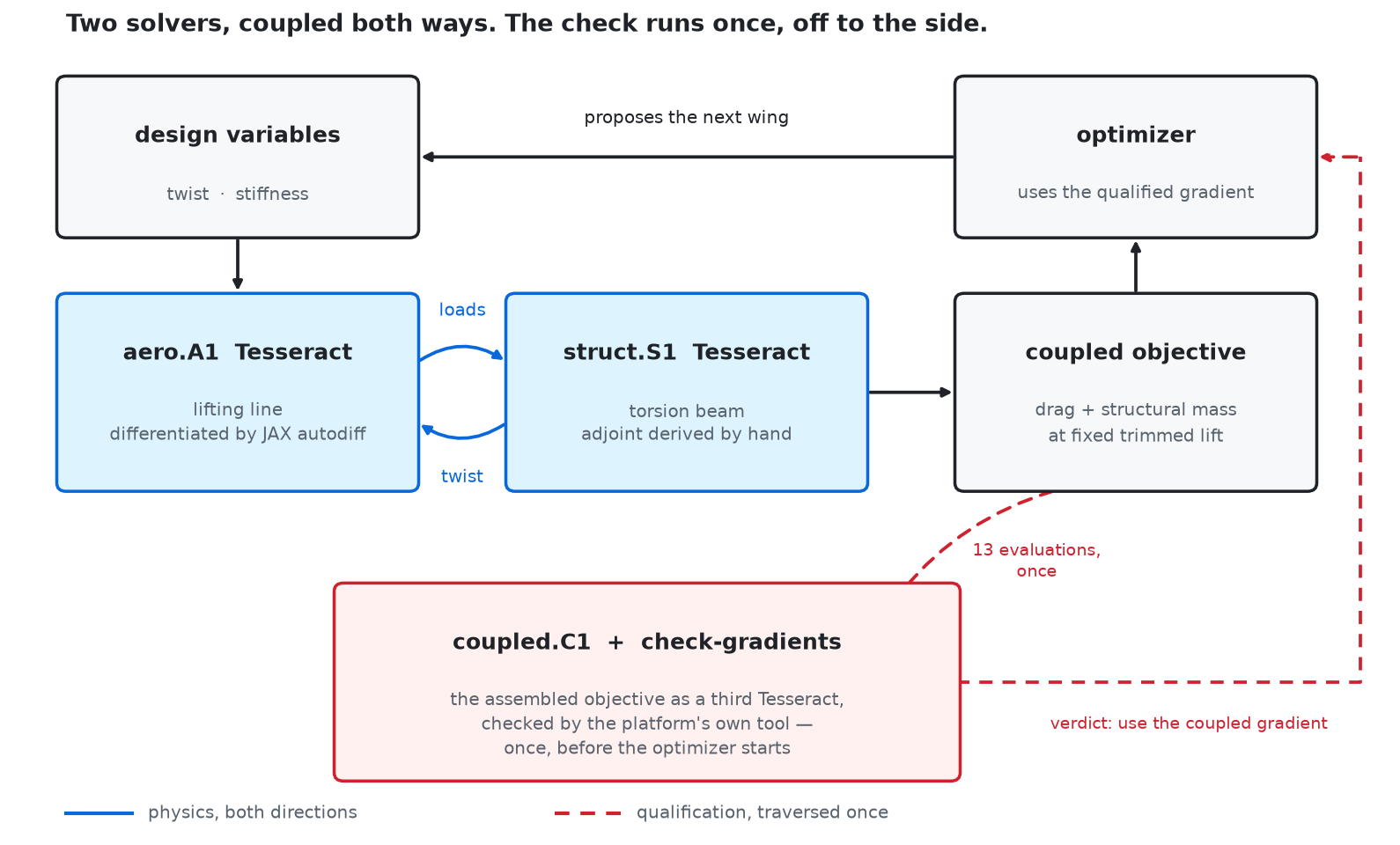
Classical lifting line in Glauert's Fourier form for the aerodynamics, forty cosine-spaced stations; a clamped cantilever torsion beam of twenty-four uniform elements for the structure. The two meshes deliberately do not match, because in real aeroelasticity they never do, and load and displacement transfer is conservative in both directions.
What that buys is a problem whose every design point can be solved exactly, which is what makes a map of 289 wings possible at all. What it costs: this is not Navier–Stokes and not a full aircraft, it is invalid at low aspect ratio, with sweep, in compressible flow or near stall, and it is static aeroelasticity with no mass axis, so it is silent about flutter.
The optimiser driven by the rigid gradient did not merely converge slowly. of the steps it took made the true objective worse, and at its worst the two gradients sat at : not merely disagreeing but very nearly exactly opposed. It was walking away.
Both arms end at the same stiffness bound, the same trimmed lift and the same mass proxy, so the entire difference is aerodynamic: more induced drag for the same lift. The spanwise load distribution in chapter 03 is where that comes from.
The result is bounded to a flight regime, and the bound was measured
Re-scoring both committed designs across speed without re-optimising either, the ranking reverses at about 57 m/s. Below that the rigid-designed wing is the better of the two, by 9.6 % at 30 m/s. The design condition is 80 m/s.
That is the shape of the claim. The cheap gradient is not wrong everywhere; it is wrong at the condition this wing was designed for, and right at conditions it was not.
The tolerance
Step along the cheap gradient and ask what fraction of the improvement the cheap gradient promised you get. Call it r̂. A design is counted against the cheap gradient when r̂ < η₁ with η₁ = 0.01, fixed in the repository before scoring.
It is a choice, and the count of 31 moves if you move it: this is a boundary defined by a declared tolerance, not a physical discontinuity. What does not move with it is the geometry. The failures stay in the soft, washed-out corner.
One round trip at a time
The coupling, run in the openThe aerodynamics hands the structure a torque. The structure hands back a twist. The twist changes the incidence, so the torque changes, and it goes round again. Below is that exchange on the coupled design, one frame per round trip, starting from an undeformed wing.
What is happening
01 Before the air acts
The first frame is the wing as drawn, before the air has acted on it: zero elastic twist everywhere. Each frame after it is one complete exchange between the two solvers.
02 One exchange at a time
The first exchange is the largest. The tip picks up 0.97 degrees, about a fifth of the twist it will finish with, and no later pass moves it that far again. Watch the tip. It overshoots nothing and approaches its final value from below, each pass leaving a fixed fraction of what is left. That fraction is the contraction factor of the loop, and it is not a free parameter: measured here it is , so about a quarter of the remaining gap closes per pass, against a dynamic pressure of of this design's divergence pressure. By the twelfth pass the tip is within 0.15 degrees of where it settles, and each pass from here closes about a quarter of what is left. The loop converges as slowly as the wing is close to diverging.
03 Where it stops
Thirty-four frames in, the tip holds against the the direct coupled solve gives, a difference of of a degree. The partitioned exchange drawn here and the single linear system the repository solves are the same answer. Which is the awkward part of the result. The designs where the cheap gradient fails are also the designs where the accurate one costs most.
Recomputed, and checked against the committed solve
The repository's core solves the coupled state directly, as one linear system, because that is cheaper and exactly equivalent. The partitioned exchange drawn here is the same system split the way the two services actually split it, iterated with the core's own operators from the committed design vector.
The last frame agrees with the direct coupled solve to of a degree, and the contraction factor measured off the frames equals the dynamic-pressure ratio to four digits, which is the behaviour the repository documents for this loop.
One wing, optimised twice
The trap, in four numbersTake the wing from chapter 01 and optimise it two ways from a common start, both to convergence: once with the coupled gradient, once with the rigid one. Then score both answers with the coupled model, because that is the only score a real wing gets.
The four numbers below are the whole result. Read the table by row and the cheap run looks like a tie. Read it by column and it is 16 % worse. The failure is invisible from inside the component that caused it.
| the wing | scored by its own model | scored by both solvers together |
|---|
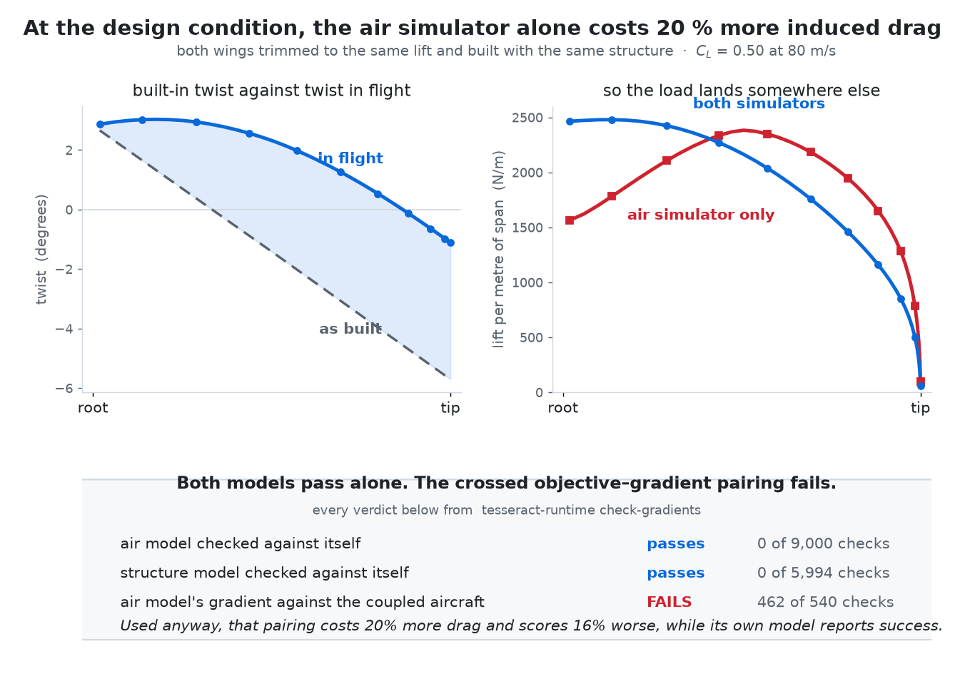
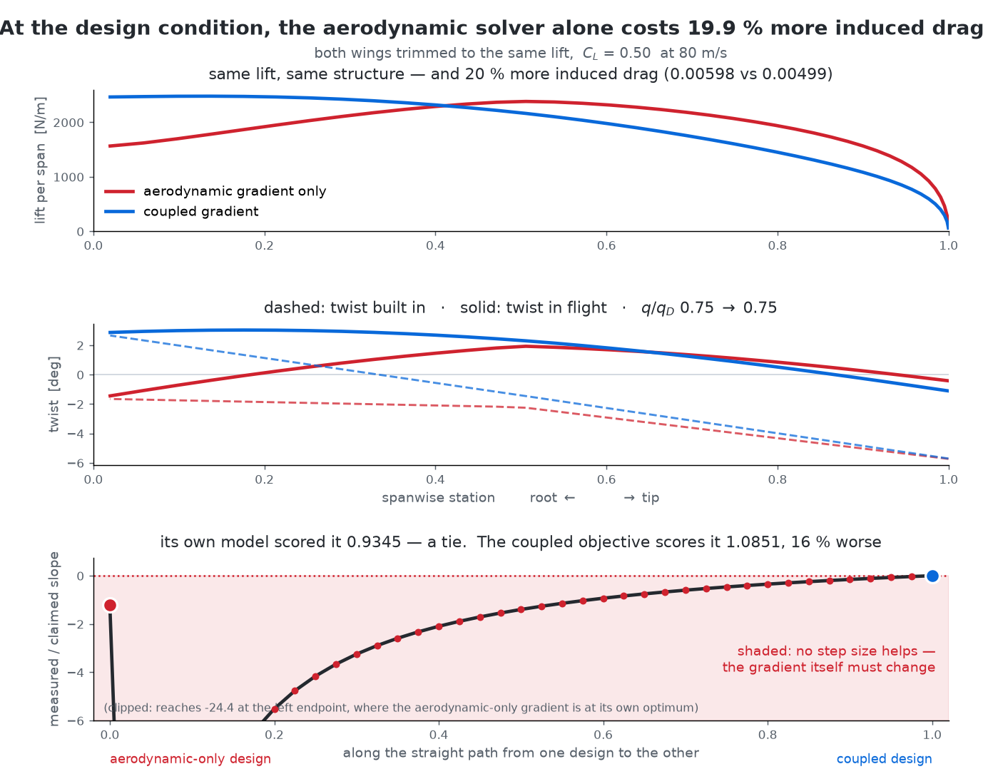
Two numbers come out of that pair and they are not the same number. At the same trimmed lift and the same structure the rigid-designed wing makes 19.9 % more induced drag, which is the aerodynamic penalty. Scored on the coupled objective the optimiser was actually minimising, the same wing lands 16.2 % worse. The second is the one that matters to a designer, because it is the number their own optimiser would have reported if it had been told the truth, and the run that produced it converged normally and declared success against its own model the whole way.
The same wing, both ways, as the study drew it
The native panels above rebuild the comparison from the run records. These are the figures the study itself produced.
Where the substitution fails
289 wingsOne design point is an anecdote. The map is the measurement: at every one of the 289 wings, both gradients are computed, a step is taken along the cheap one, and the fraction of the promised improvement it actually delivers is recorded. That fraction is r̂. The field beside this is r̂ everywhere, and a wing is counted against the cheap gradient when r̂ < 0.01.
The 31 that fail sit in one corner and it is a physically sensible one: the three most washed-out tip twists, −5.7°, −5.2° and −4.6°, and only in the softer eleven of the seventeen stiffness rows, which is dynamic pressure from 37 % of divergence up past it. Nothing fails at the stiff end. In 30 of the 31 the step does not merely buy nothing, it makes the wing worse.
That shape is the repository's own account of the mechanism, and it is geometric. A wing with a lot of built-in washout, soft enough that the air twists it back, ends up flying with its geometric twist nearly cancelled. Elastic washin against geometric washout: the same picture as the figure at the top of the page, taken to the point where it dominates.
The deeper reason is in one column of the record, and it is the sharper half of the result. At fixed lift the rigid objective contains no dynamic pressure at all, so the rigid gradient returns the same vector at every flight condition the aircraft will ever see: norm 3.7250, spread exactly zero. Its error is a fixed quantity, while the coupled gradient shrinks as the design approaches the coupled optimum. A fixed error dominates a shrinking signal, and the place where that happens is the last neighbourhood an optimiser visits.
Neither coupling nor proximity does it alone
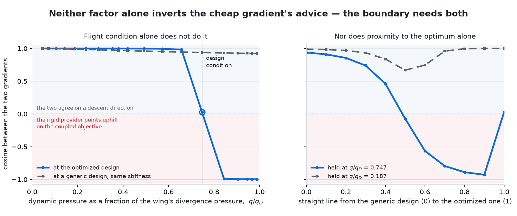
Write e for the error in the cheap gradient. While ‖e‖ / ‖g‖ < 1 the cheap direction is still a descent direction, which is Carter's relative-gradient-error condition (SIAM J. Numer. Anal. 28, 1991). Coupling grows the numerator; standing near the coupled optimum shrinks the denominator. One factor alone moves the ratio, and neither alone pushes it past one.
Both controls are in the record. Sweeping the flight condition at a stiffness no optimiser chose, the two gradients never fall below a cosine of 0.922 anywhere up to 99 % of divergence pressure, and no step ever increases the coupled objective. Holding the flight condition at a fifth of divergence pressure and walking the design in to the optimum, the cosine dips to 0.67 and recovers without changing sign. Only at the design condition does the same walk cross zero and reach −0.929, and the ratio passes one at q/q_D = 0.49.
Four cheap ways to guess, scored
The negative resultFour warning signs were declared before scoring, each with its threshold fixed in advance: dynamic pressure against divergence, maximum elastic twist, a twist-cancellation ratio, and how much load has moved inboard. Each is the kind of number a designer already has.
The bar they have to clear is low. Only 31 of the 289 designs fail, a base rate of 10.7 %, so a warning sign that simply says "no" every time is right 89.3 % of the time. The best of the four reaches a Matthews correlation of 0.10 against that, and the one drawn from this study's own account of the mechanism scores worst of all. Accuracy is the wrong column to read; the two error columns beside it are the ones that carry the result.
| warning sign | true pos | false pos | missed | accuracy |
|---|
Every one of them is monotone in flexibility, so every one of them fires at the soft end of the sweep. The median position of their positives sits at column 8, 9, 9 and 10 of seventeen; the failures sit at column 1. They are not weak detectors of the boundary. They are looking in the other half of the design space, which is why all four land below a rule that simply predicts "no" every time.
All four read operating-point state, while the governing ratio has a design-space quantity in its denominator that operating-point state cannot observe. That accounts for these four scores without ruling out a better indicator.
What a negative result is worth
The useful result here is the negative one. It does not say the rigid-wing gradient is unsafe: for most of this design space it is fine. It says that on this wing, the cheap proxies a designer would reach for do not locate the boundary, so the options are to compute the coupled gradient or to accept that you do not know which side you are on. The map, the comparators and their thresholds are all in a public repository, so the result can be disagreed with in the only way that counts.
What this does not establish
- One reduced-order wing, six design variables with the map swept over two of them, one flow condition. Nothing here transfers to a real aircraft without redoing it.
- The mechanism offered for the failure region, elastic washin cancelling geometric washout, is the repository's own reading of the map's shape. It is consistent with where the failures fall and with the fixed-error argument, and it is not established by an independent experiment.
- Four comparators, one threshold each. A tuned threshold, or a fifth comparator, might do better; that is a different experiment.
- Built quickly and with AI assistance. It is a small, checkable result, not a research contribution.
- The boundary is defined by a chosen tolerance on gradient agreement. Move the tolerance and the 31 moves with it.
- Static aeroelasticity only. There is no mass axis, so no flutter, and on an unswept wing flutter can precede divergence. The model is silent about that.
- Both optimisation arms drive torsional stiffness to its lower box bound, ending at 74.7 % of divergence pressure against 37.1 % at the start. A box bound stops them, not a stability constraint.
Four minutes of the tool being driven
Demo and accessEverything above is a still argument about a moving system. This is the system moving: four minutes of the tool being driven end to end.
The repository is public under Apache-2.0, at github.com/MasonShopperly/misFit. It holds the committed records every number here is drawn from, a replay that reads them in under a second, and the full route to re-run the sweep and both optimisations on a CPU. Nothing here needs a GPU or a licence to check.
It was built for Track 02, multi-physics and coupled systems, of the Tesseract Hackathon 2026 run by Pasteur Labs.