Independent · ongoing
A new case swaps a mesh and inherits every convergence, discretisation and post-processing decision unchanged.
An OpenFOAM external-aerodynamics pipeline built around the Ahmed body, with the discipline in the templates rather than in someone's memory, and one study.
A single external-aerodynamics case has enough moving parts (geometry, mesh, boundary conditions, solver, closure, post-processing) that untracked variation drifts the answer faster than the physics does. The pipeline's whole purpose is that the parts which decide what is measured are fixed in the template, and only the part under study moves.
Across the 33 cases of the mesh-independence sweep the dictionary that defines the force measurement has exactly one version, so every case measures drag the same way. The six runs that settled were not otherwise identical: they also vary the inlet turbulence and, on one run, the momentum scheme, so the spread between them is not attributable to the mesh. What follows is that comparison, plus the flow field the baseline case produced: sampled from the solver's own written fields.
It also found something. Holding the measurement fixed is what makes a discrepancy visible instead of absorbable, and the discrepancy this one surfaced is in the geometry it was run on. Chapter 04.
The baseline case, M22
- U∞
- 30 m/s
- ν
- 1.5 × 10⁻⁵ m²/s
- ReL
- 2.09 × 10⁶
- cells
- 7 922 294
- iterations
- 3 600
- ground
- fixed, no-slip
- wall
- functions, ȳ⁺ 74.8
- Cd
- 0.2281
The flow the baseline case produced
The evidenceOne object. Every state below is the same converged solution read a different way: the symmetry plane in two quantities, then a series of cross-planes stepping from the slant leading edge into the near wake. Every frame is sampled from the solver's own field files.
Narration
01 The symmetry plane
Streamwise velocity through the centreline, as a fraction of the 30 m/s freestream. Everything below zero is reversed flow: a closed recirculation sitting immediately behind the slanted rear, and a second one under the body. The same plane in pressure coefficient. The stagnation point reaches Cp = 1.00, which is the arithmetic the normalisation has to satisfy and the first check that the sampling is sound.
02 Across the slant
Streamwise vorticity at the slant leading edge. The flow has just been asked to turn downward and the side edges are already shedding. Half way down the slant, a counter-rotating pair is clearly formed: one sign each side of the centreline. Near the base, the pair has moved inboard and strengthened.
03 Into the wake
At the base, the longitudinal pair sits above the blunt-base recirculation rather than in it. Sixty millimetres downstream the peak magnitude has fallen and the pair has spread. Three hundred millimetres downstream it is what it was at the base, and diffuse. The structures are present and they spread rather than disappear, which is what a steady RANS closure on this mesh is able to say about them; the next chapter measures it.
The field, as the solver rendered it
The panels above are rebuilt from the extracted arrays. These two are the renders themselves, and they carry the one thing an extracted slice cannot: what the structure looks like in three dimensions.
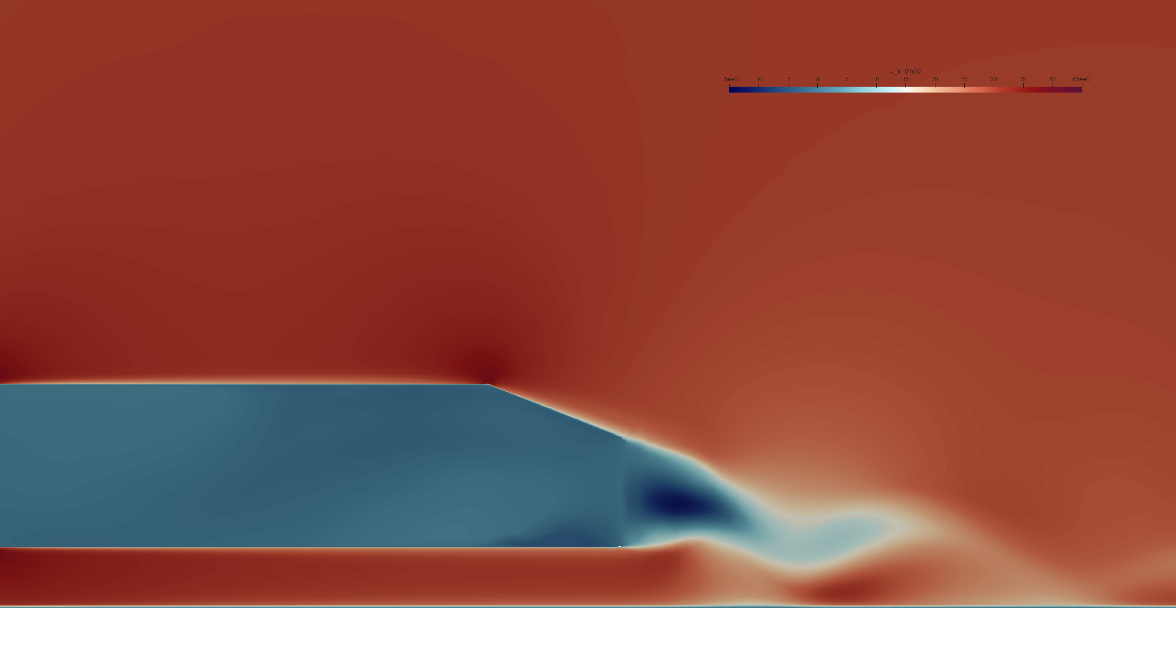
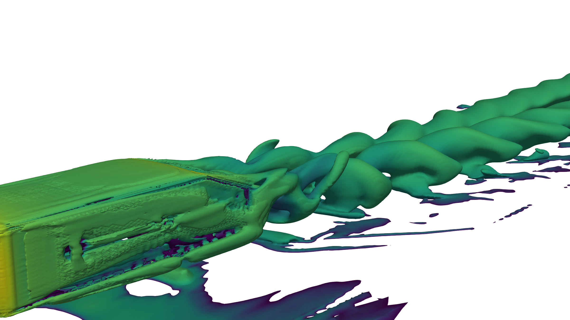
The wake does not fade. It spreads.
CirculationA slanted-back bluff body at this angle does something specific: the flow spilling off the two side edges of the slant rolls into a pair of counter-rotating longitudinal vortices, and those vortices hold the flow attached over a surface that ought to have separated. Looking at the planes tells you the pair gets fainter downstream. Integrating them tells you that at 300 mm its circulation is back to the base value, with a dip between.
Circulation is the area integral of vorticity over one vortex, and it is the quantity that is conserved when a vortex diffuses. Both numbers below are computed here from the committed cross-plane arrays: the same-sign vorticity summed over the half-plane one vortex occupies, with nothing fitted.
The same integration gives the core's position: the intensity-weighted centroid of one vortex, plotted from behind. Circles are the eight stations, from the slant leading edge to 300 mm downstream. The rectangle is the body's own cross-section at the base.
Those are the planes the numbers above were measured on. Each panel is scaled to its own peak, because a shared scale would flatten the last three into grey, and the peak is printed instead so the comparison a shared scale would have made is still available.
What the extract carries
The usual way to show a vortex system is an isosurface of the second invariant of the velocity gradient tensor, which needs all nine gradient components through the volume. What was sampled out of this case is the streamwise component of vorticity on a set of planes: one number per point rather than nine.
For a longitudinal pair that is not a compromise. Streamwise vorticity on cross-planes is the standard diagnostic for exactly this structure, it separates the two senses of rotation by sign, and it is the only form in which circulation can be integrated directly. An isosurface would show the pair as a tube, and would also show the slant shear layer and the ground boundary layer, which this deliberately does not.
Steady RANS, and what that costs the picture
Every case in this study is a steady SIMPLE solve with a two-equation closure. The longitudinal pair is a genuinely steady structure and is the part of this wake a steady solver represents best.
The recirculation behind the base is not. In reality it is unsteady and shed; here it is a time-averaged picture of an unsteady thing, and nothing on this page carries any unsteady content at all. The bubble length quoted above is therefore a time-averaged length, not an instantaneous one.
What the sweep does, and does not, show
The limit of the claimSix runs reached a settled tail and are plotted. Two did not settle and are not plotted:
Read the settled six left to right and Cd does not settle with them.
That is the result of this study. Grid independence needs a refinement ratio around 1.3 in cell size across at least three levels: roughly 2.2× in cell count per level. The six settled runs span 7.88 M to 10.77 M, a factor of 1.37 in count and about 1.11 in size. It is not wide enough to demonstrate independence, and it does not. Nor is it one mesh family run identically: M22 and M24 share a mesh to the cell and differ in inlet turbulence, M29 has a third inlet setting, and M34 uses a different momentum scheme from the other five. The spread is not attributable to the mesh. What the sweep does establish is that every case measured drag through the same force dictionary.
What the run was checked on
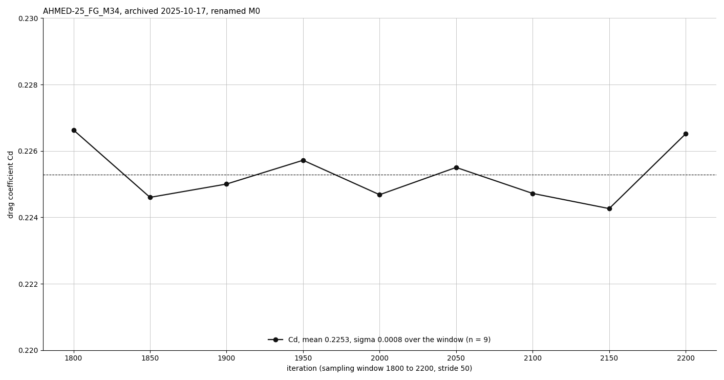
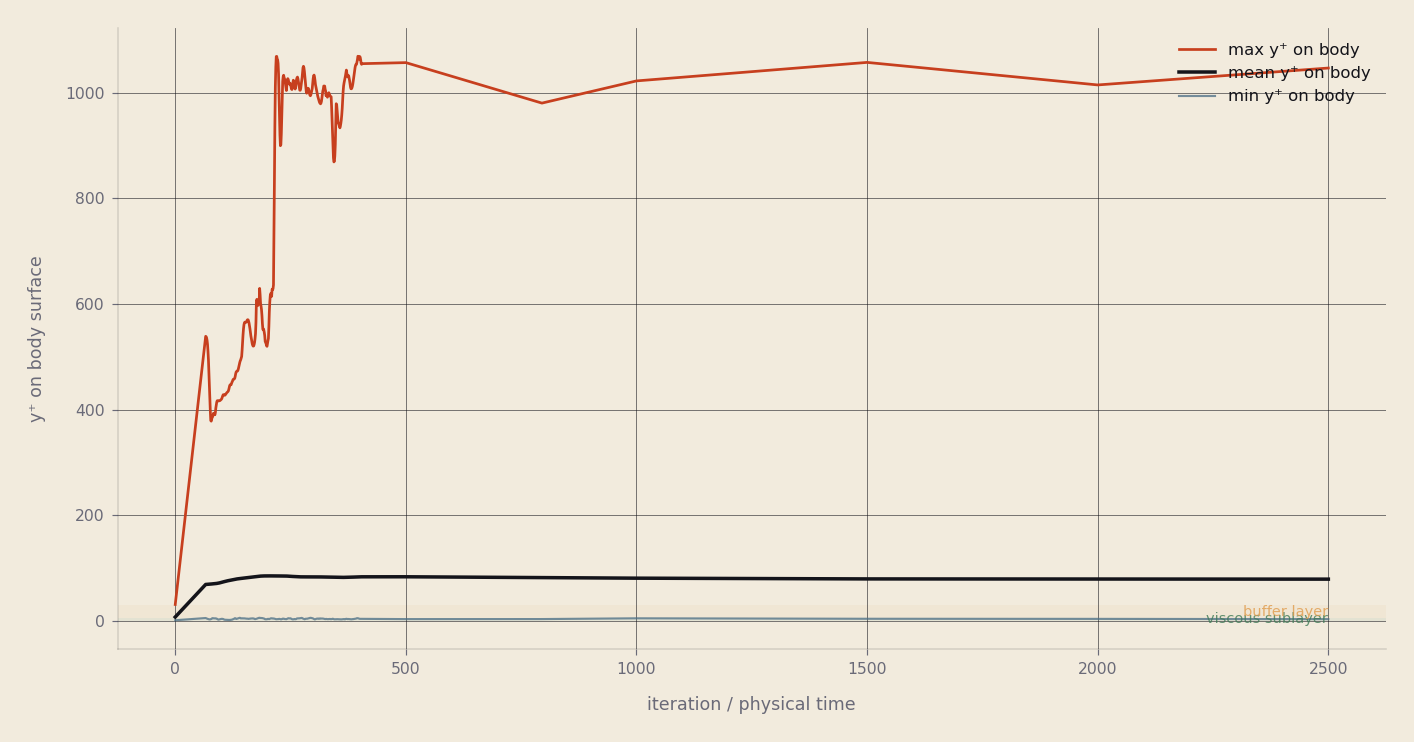
A force coefficient means nothing without the two figures beside it: how far it had settled, and whether the mesh was resolving the wall at all. Both are from the archived run AHMED-25_FG_M34 (renamed M0, 8.4 M cells), which is neither the M22 baseline above nor the 9.75 M-cell M34 in the sweep.
The geometry the sweep was run on
What the discipline caughtEvery coefficient quoted above is normalised by a reference area, and every comparison to published work assumes a shape. Both were checked against the triangulation the solver meshed: constant/triSurface/body.stl, byte-identical in all four converged cases.
Length and width are the Ahmed body's. Height, ground clearance and slant angle are not, and they are wrong together: scaling the standard body by 0.852 in z alone gives a height of 0.2454 m and turns a 25° slant into atan(0.852·tan 25°) = 21.67°, which is what the triangulation measures to three decimals.
The reference area declared to the force calculation is 0.112032 m²: exactly 0.389 × 0.288, the standard body's frontal area. The frontal area of the triangulation, computed exactly from the mesh, is 0.095459 m². The declared reference is 1.1736× the geometry's own.
What that does and does not affect. The sweep compares cases that all share this geometry and this reference, so the mesh comparison above is unaffected: a constant factor divides out of it. What it forbids is the comparison this case's name invites: these coefficients are not on the same footing as published 25° Ahmed-body data, and none is set beside them here. The cause of the scaling is not established here; only the measurement is.
| quantity | this STL | Ahmed 1984 | ratio |
|---|
Rows that disagree are marked. Standard values as tabulated in the ERCOFTAC AC1-05 case description of Ahmed, Ramm & Faltin (1984), SAE 840300.
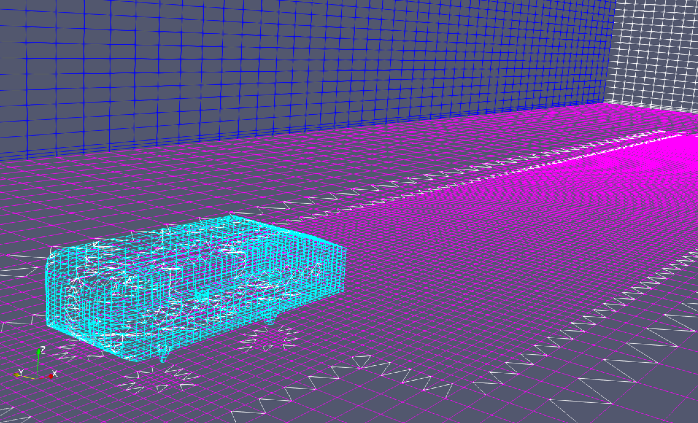
The strongest thing the case can say is not a drag coefficient. It is that a pipeline built to hold the measurement fixed did exactly that, and the first thing it caught was an inconsistency in its own baseline case: a body scaled in z and a reference area that was never rescaled with it. A study with the force dictionary edited per case would have absorbed that as scatter and nobody would have looked. Here it is a 1.1736× factor with a number on either side of it.
The repair belongs in the case: re-cut the geometry or declare the geometry's own frontal area, then re-run. Until that happens the mesh comparison stands, the flow field stands, and the coefficient stays off the literature axis.
What this does not establish
- Not a validated drag prediction. The geometry is a 21.67° slant with a 0.2454 m height, and the coefficients are normalised by the standard body's frontal area rather than its own. No comparison to published Ahmed-body coefficients is made on this page; the y+ note makes a drag-level one, and with this slant and reference area it can only be drag-level.
- Not grid independence. Six settled runs spanning 7.88 to 10.77 M cells is a refinement ratio of about 1.11 in cell size, and they differ in inlet turbulence and, on one run, the momentum scheme. Cd varies by across them with no monotone trend.
- Every case in the repository runs simpleFoam: steady SIMPLE, with endTime as an iteration count. Nothing here is time-resolved, so the vortex structures are a steady RANS closure's time-averaged picture of them and carry no unsteady content at all. The two cases named _SAS and _DES also declare simpleFoam and produced no result.
- Wall treatment is the wall-function regime. Measured body y⁺ on the M22 baseline averages 74.8, inside the 30–300 band, but reaches 840 at its maximum, which is outside it. Not resolved to the wall anywhere.
- Sampling gaps: a cutting plane returns values where it crosses cells, so 27 % of the rendered grid had no sample and takes the value of the nearest one. For a finite-volume field, which is piecewise constant over a cell, that is what the solver's data says holds there, but it is a rendering choice.
What I would do differently
Earlier benchmarking would have saved time. My first Ahmed body run had enough drag error that I spent longer than I should have chasing mesh sensitivity, when the shortcut, binding the geometry's reference dimensions and running a known-good reference case alongside every new one, belonged at the top of the template.
Next is the DrivAer geometry, which is a real car shape rather than a bluff body with a slant, and it is where a template that only ever worked on the Ahmed body would stop being useful.